The 7/16 DIN connector (7/16 DIN male/female, IEC 61169-4 compliant) remains the industry-standard high-power coaxial interconnect for cellular base stations, Distributed Antenna Systems (DAS), macro towers, and broadcast transmission systems. Named after its physical metric dimensions—a 7 mm inner conductor inner diameter and a 16 mm outer conductor inner diameter—this heavy-duty 50 Ω threaded coupling mechanism provides exceptional passive intermodulation (PIM) performance, mechanical strength, and environmental sealing.
When specifying RF jumpers, surge protectors, or antenna feed lines, understanding the exact mechanical interface, thread pitch, contact dimensions, and mating torque tolerances is critical to avoiding signal degradation, contact damage, or PIM spikes.
This guide breaks down the precise dimensional blueprints, thread tolerances, material standards, and real-world installation requirements for 7/16 DIN connectors manufactured to IEC 61169-4, CECC 22190, and DIN 47223 standards.
Core Dimensional Specifications & Mechanical Blueprint
A standard 7/16 DIN interface operates up to 7.5 GHz, handling RF power levels exceeding 3 kW at 1 GHz (continuous power). To maintain a low Voltage Standing Wave Ratio (VSWR ≤ 1.10 up to 3 GHz) and maintain contact pressure under severe wind and vibration, critical dimensional features must strictly comply with international standards.
Interface Dimensions Summary (IEC 61169-4)
| Interface Element |
Male Connector (Plug) Specification |
Female Connector (Jack) Specification |
Critical Tolerance / Notes |
| Inner Conductor (Center Pin/Socket) |
Outer Dia: 3.00 mm ± 0.02 mm |
Inner Hole Dia: 3.00 mm nominal (spring contact) |
Beryllium Copper (BeCu) recommended |
| Outer Conductor Contact |
Inner Dia: 16.00 mm (+0.04 / -0.00 mm) |
Outer Contact Dia: 16.00 mm (+0.00 / -0.04 mm) |
Silver-plated solid brass body |
| Thread Size & Pitch |
M29 x 1.5 - 6g |
M29 x 1.5 - 6H |
Standard Metric Fine Thread |
| Coupling Nut Hex Size |
32 mm Hex / Flange diameter optional |
N/A (Fixed Threaded Outer Body) |
Requires calibrated torque wrench |
| Mating Engagement Depth |
10.50 mm - 11.20 mm |
10.50 mm - 11.20 mm |
Prevents pin bottoming & PIM degradation |
| Dielectric Outer Diameter |
16.00 mm (PTFE Teflon) |
16.00 mm (PTFE Teflon) |
Low dielectric constant (εr ≈ 2.1) |
Thread Mechanics & Mating Torque Requirements
The 7/16 DIN connector uses an M29 x 1.5 metric fine thread. Unlike quick-lock or smaller thread interfaces (e.g., N-Type M16x1 or 4.3-10 M20x1), the robust M29 thread structure allows high contact forces without thread stripping or body distortion.
Torque Specifications & Installation Mechanics
To achieve optimal Passive Intermodulation (PIM ≤ -163 dBc @ 2 x 20W / 43 dBm), proper torque application is non-negotiable.
- Recommended Installation Torque: 25 N·m to 30 N·m (18.4 ft-lbs to 22.1 ft-lbs)
- Minimum Retaining Torque: 20 N·m (14.7 ft-lbs)
- Maximum Safe Torque Limits: 35 N·m (25.8 ft-lbs)
Technical Warning: Over-Torquing vs. Under-Torquing
- Under-Torquing (< 20 N·m): Leads to insufficient physical contact between the outer conductor mating faces. Micro-gaps under mechanical vibration generate non-linear junction capacitance, triggering severe PIM spikes and high VSWR.
- Over-Torquing (> 35 N·m): Risk of deforming the center pin receptacle or galling the silver-plated outer conductor face, permanently ruining the connector's intermodulation rating.
Contact Geometry & Material Selection Logic
High-power B2B RF deployments demand strict control over surface finish, base metals, and plating layers to ensure long-term corrosion resistance and thermal stability.
Material & Plating Matrix
| Connector Component |
Standard Material Specification |
Surface Plating & Thickness |
B2B Procurement Purpose |
| Outer Body & Thread |
Free-cutting Brass (HPb59-1 / CuZn39Pb3) |
White Bronze (Tri-Metal / Sucoplate) or Silver (Ag ≥ 5 µm) |
Superior corrosion protection (240h Neutral Salt Spray) |
| Male Center Pin |
Solid Brass / Tellurium Copper |
Silver Plated (Ag 5 µm - 8 µm) with nickel underplate |
Maximum conductivity & low contact resistance |
| Female Inner Socket |
Beryllium Copper (C17200 / CuBe2) Heat Treated |
Silver Plated (Ag 5 µm - 8 µm) |
Maintains elasticity over >500 mating cycles |
| Insulator / Dielectric |
Virgin PTFE (Polytetrafluoroethylene) |
Unplated / Solid Virgin PTFE |
Thermal resistance from -40°C to +155°C |
| Sealing O-Ring |
Silicone Rubber or EPDM |
IP68 Weatherproof Rating |
Prevents water ingress in outdoor macro towers |
7/16 DIN vs. 4.3-10 vs. N-Type: Dimensional & Performance Comparison
In modern 5G Macro and DAS deployments, engineers frequently evaluate replacing legacy 7/16 DIN connectors with compact interfaces like 4.3-10 or traditional N-Type.
| Specification Metric |
7/16 DIN Interface |
4.3-10 Interface |
N-Type Interface |
| Outer Thread Spec |
M29 x 1.5 |
M20 x 1.0 |
5/8-24 UNEF-2A/2B |
| Recommended Torque |
25 - 30 N·m |
5 N·m |
0.7 - 1.1 N·m |
| Frequency Range |
DC to 7.5 GHz |
DC to 12 GHz |
DC to 11 GHz / 18 GHz |
| PIM Rating (2x43 dBm) |
Typical -163 dBc |
Typical -166 dBc |
Typical -140 to -155 dBc |
| Max RF Power (1 GHz) |
~3.0 kW |
~1.2 kW |
~600 W |
| Footprint Flange Size |
Large (32mm Hex Body) |
Compact (~40% smaller footprint) |
Medium |
| Primary Use Case |
High-Power Feeders, Macro Antenna Ports |
High-Density 5G Small Cells, DAS |
Low-Power Jumpers, Test Equipment |
Quality Control & Factory Testing Protocols
To guarantee every batch of 7/16 DIN cable assemblies and adapters meets international telecom operator standards (e.g., Vodafone, China Mobile, AT&T specs), our factory implements a 5-Step Quality Assurance Routine:
- Precision CMM & Optical Gauge Inspection: 100% verification of inner conductor 3.00 mm diameter, M29 thread pitch, and outer conductor mating depth within ±0.01 mm tolerance.
- PIM Testing (Dynamic & Static): Tested with IEC 62037 compliant 2x20W (43 dBm) carriers at 800/900/1800/2100 MHz bands, verifying passive intermodulation does not exceed -163 dBc.
- Helium Mass Spectrometer Leak Detection / IP68 Hydrostatic Test: Submerged and pressure-tested up to 1 meter depth for 24 hours to ensure zero moisture intrusion across the O-ring interface.
- Plating Thickness Analysis (XRF Gauge): Verification of silver coating (≥5 µm) and anti-tarnish passivation to eliminate contact corrosion in coastal environments.
- Mechanical Cycle Endurance: 500 minimum mating/unmating cycles under torque testing without degradation of spring retention force or contact plating.
Procurement & Custom OEM Options
As a direct B2B RF connector manufacturer, CNRF Connectors provides tailored customization for cable assembly builders, antenna manufacturers, and system integrators.
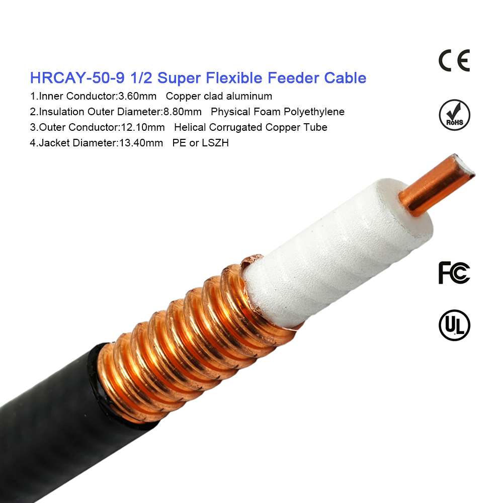
- Supported Cable Types: 1/2" Flexible & Superflexible, 7/8" Feeder Cable, LDF4-50A, Corrugated Copper Tube, RG214.
- Mounting Configurations: 4-Hole Flange Panel Mount, Bulkhead O-Ring Mount, Right Angle & Straight Solder/Crimp Interfaces.
- MOQ & Lead Times: Standard items available from stock; custom OEM orders processed in 7–14 days with full ISO9001, RoHS, and REACH compliance certifications.
For detailed engineering drawings, CAD models (.STEP files), or volume B2B quotes, visit our main B2B portal at WORLDPEAK.
 EN