EN

EN
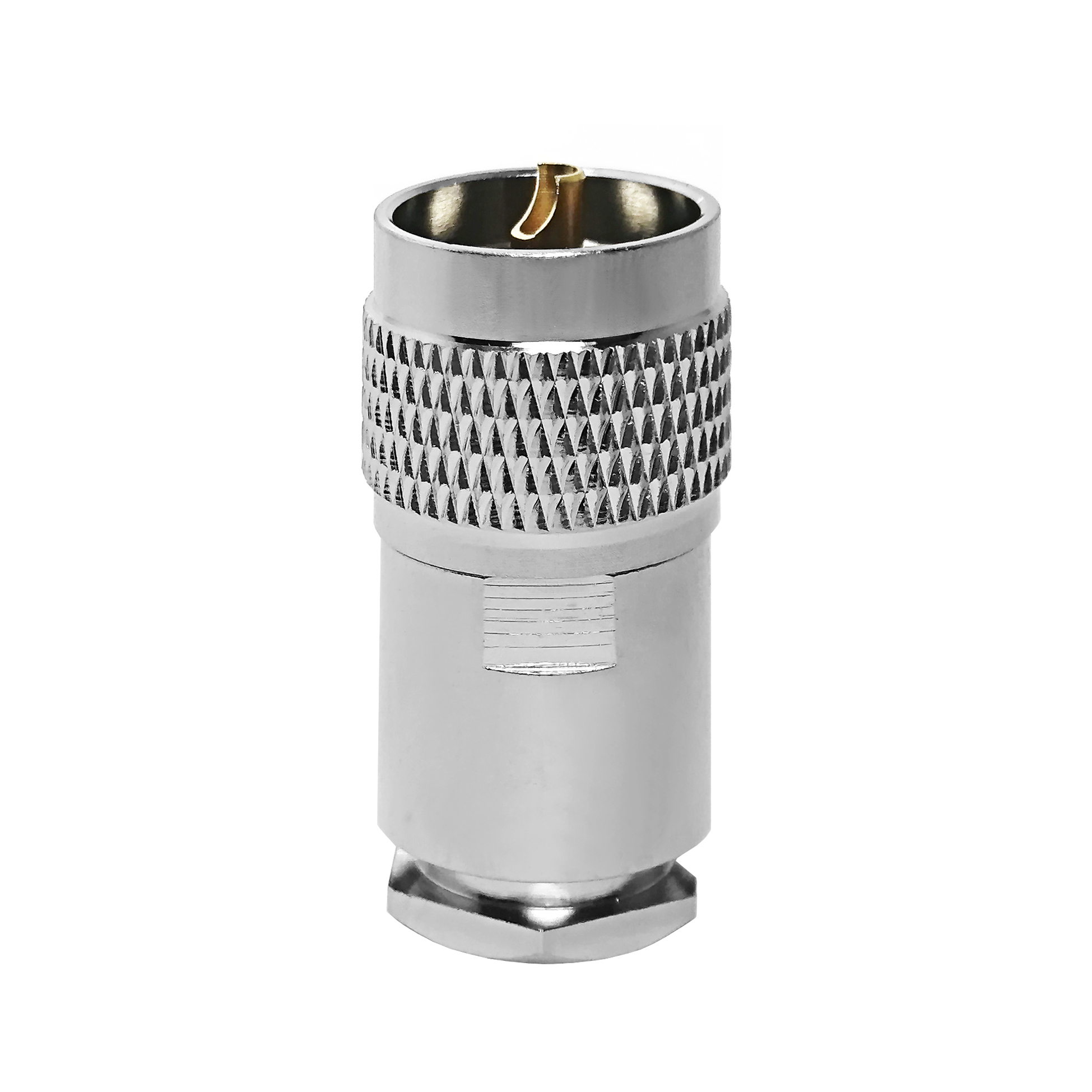
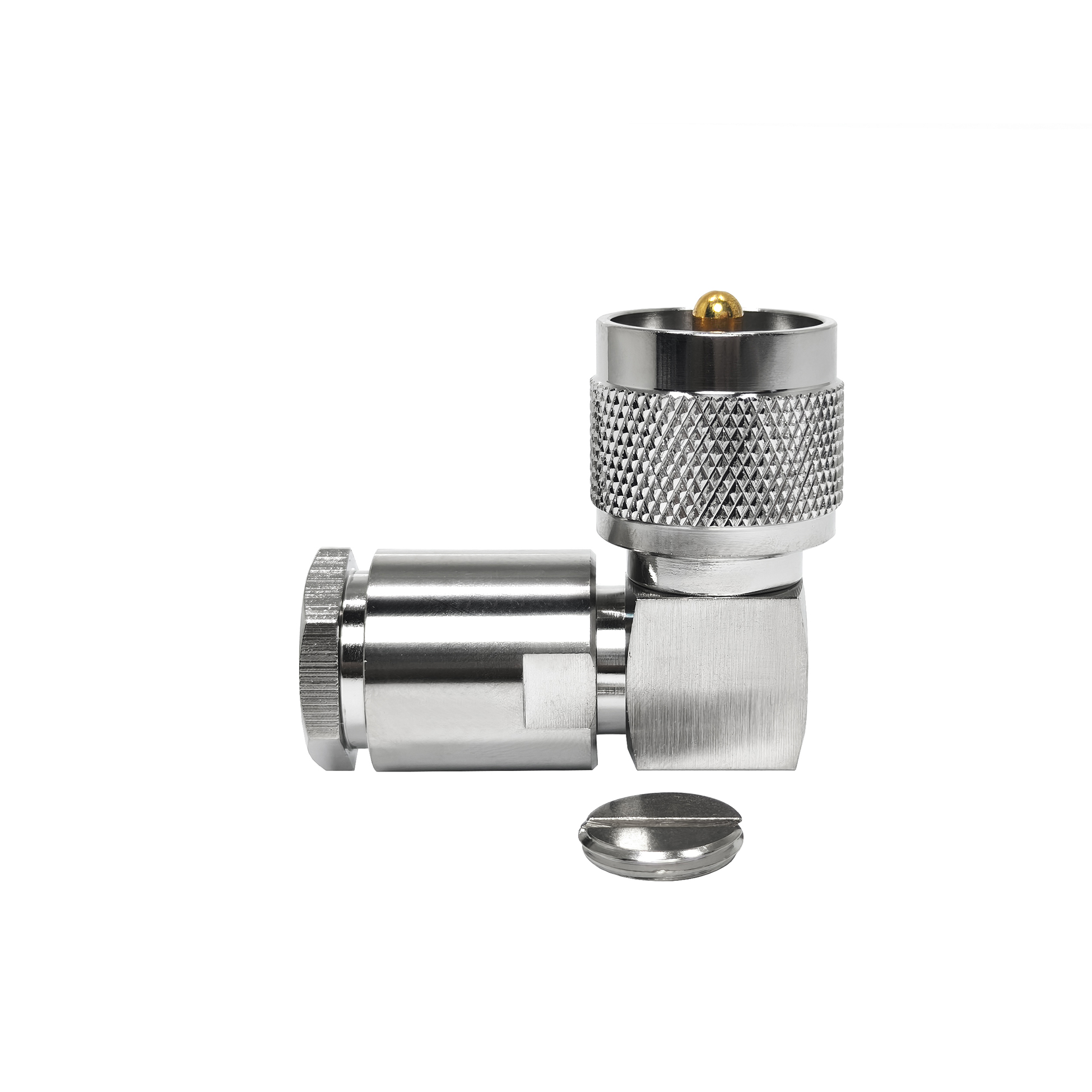
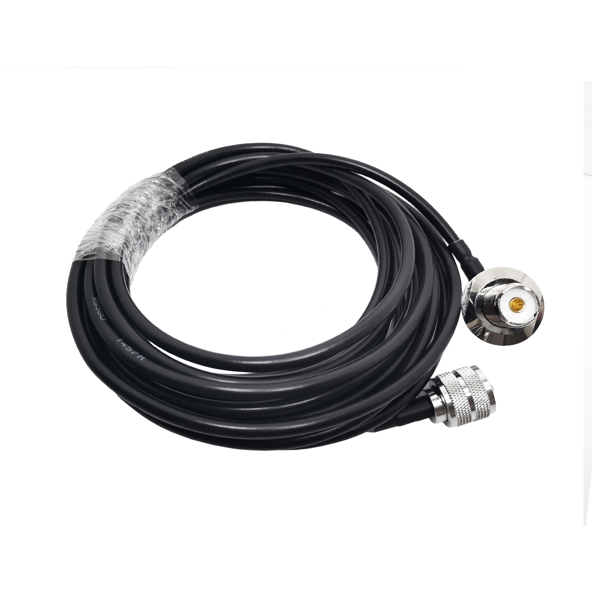
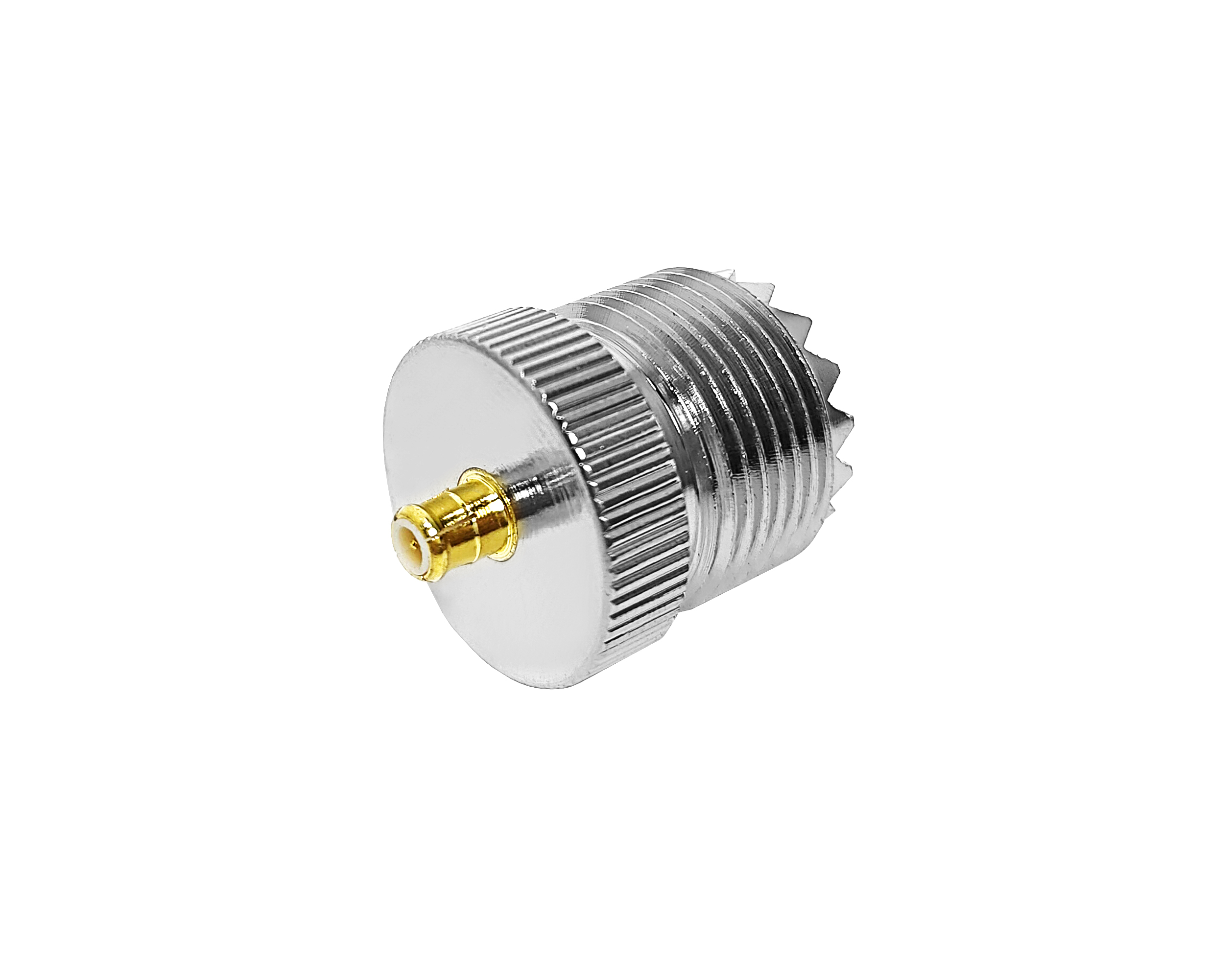
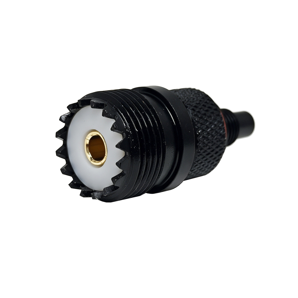
A UHF connector is a 50 Ω coaxial interface with threaded, 5/8-24 unef.
The most common application area is HF and VHF amateur radio stations.
This page covers the interface, one reference specification, every interface in our range a UHF connector can be adapted to, and the cable families we pair with it.
Parameter |
Specification |
Interface |
UHF |
Impedance |
50 Ω |
Coupling |
Threaded, 5/8-24 UNEF |
Interface frequency class |
Historically a low-frequency interface rather than a modern UHF one, so read the name as a design lineage and not as a band label. The reference part quoted below is rated 0–4 GHz (factory nominal). |
Gender |
Male (centre pin) / Female (centre socket) |
Body styles |
Straight, right-angle, bulkhead, panel and clamp bodies |
Interface standard |
MIL-STD-348 / IEC 61169 series |
Performance data |
Full datasheet on request |
The figures below are a reference point for the series. They belong to one part – UHF male connector for 1/2 in cable – and are nominal factory values, not measured values. Other parts in the series differ.
Item |
Value |
Reference part |
UHF male connector for 1/2 in cable |
Drawing number |
Available on request |
Revision |
Current revision |
Parameter |
Value |
Impedance |
50 Ω |
Frequency range |
0–4 GHz (factory nominal) |
VSWR (straight) |
≤ 1.25 |
Withstand voltage |
2000 V rms |
Working voltage |
750 V |
Contact resistance – centre |
≤ 5 mΩ |
Contact resistance – outer |
≤ 5 mΩ |
Insulation resistance |
≥ 5000 MΩ |
Parameter |
Value |
Temperature range |
-40 °C to +85 °C |
Durability |
> 500 matings |
Part |
Base material |
Plating |
Body |
Brass |
Silver plated |
Centre conductor |
Brass |
Gold plated |
Insulator |
PTFE |
— |
Source: WorldPeak factory specification sheet (nominal values, not measured). Interface capabilities quoted here describe the connector standard, not the performance of any particular part.
A UHF connector joins to almost every other interface we make. Which adapter you need depends on whether both ends sit in the same impedance system, which interface sets the frequency ceiling, and whether the joint is made on a rigid adapter or a pre-made pigtail. All 28 other interfaces are listed below.
⛔ PL-259 (UHF) and N-type share a 5/8-24 thread. The thread engages, the interface geometry does not match, and forcing them together damages the centre contact. Use an N male to UHF female (SO-239) adapter.
Interface |
Verdict |
Adapter required |
Typical use |
BNC |
✅ Direct |
BNC |
Test, video, lab |
HN type |
✅ Direct |
HN type |
High-voltage RF |
LC coaxial |
✅ Direct |
LC coaxial |
Legacy broadcast |
N-type |
⛔ Do not force |
N male to UHF female (SO-239) |
Base station / antenna |
SC coaxial |
✅ Direct |
SC coaxial |
Legacy industrial RF |
TNC |
✅ Direct |
TNC |
Vehicle / marine radio |
10-32 |
✅ Direct |
10-32 |
Compact panels |
BMA |
✅ Direct |
BMA |
Rack blind-mate / ATE |
MCX |
✅ Direct |
MCX |
GPS / wireless module |
NEX-10 |
✅ Direct |
NEX-10 |
5G small cell |
QMA |
✅ Direct |
QMA |
Dense RRU panels |
SMA |
✅ Direct |
SMA |
Test, Wi-Fi, GPS |
SMB |
✅ Direct |
SMB |
Rack / panel wiring |
SMC |
✅ Direct |
SMC |
Instrument panels |
SMP |
✅ Direct |
SMP |
Board-to-board blind mate |
SSMA |
✅ Direct |
SSMA |
Microwave modules |
FME |
✅ Direct |
FME |
Mobile antenna pigtail |
4.3-10 |
✅ Direct |
4.3-10 |
5G / 4G antenna port |
7/16 DIN |
✅ Direct |
7/16 DIN |
Macro site / broadcast |
1-5/8 EIA |
✅ Direct |
Flange to 1-5/8 EIA |
High-power feeder |
3-1/8 EIA |
✅ Direct |
Flange to 3-1/8 EIA |
High-power HF feeder |
7/8 EIA |
✅ Direct |
Flange to 7/8 EIA |
Base station feeder |
CRC9 |
⚠️ Conditions |
Pre-made pigtail |
Cellular dongle |
TS9 |
⚠️ Conditions |
Pre-made pigtail |
Cellular modem |
U.FL/IPEX |
⚠️ Conditions |
Pre-made pigtail |
Wi-Fi / LTE module |
1.0/2.3 (75 Ω) |
⚠️ Conditions |
50/75 Ω matching pad |
Central office / DSL |
1.6/5.6 (75 Ω) |
⚠️ Conditions |
50/75 Ω matching pad |
Telecom 75 ohm |
F-type (75 Ω) |
⚠️ Conditions |
50/75 Ω matching pad |
CATV / satellite |
Frequency rule for UHF: the lower-rated interface wins, then the adapter caps it again. On a medium-size line the practical ceiling is often set by the cable rather than by either connector, so send us the band and the cable and we will confirm which end limits it.
Direct: 21 interfaces. With conditions: 6. Do not force: N-type.
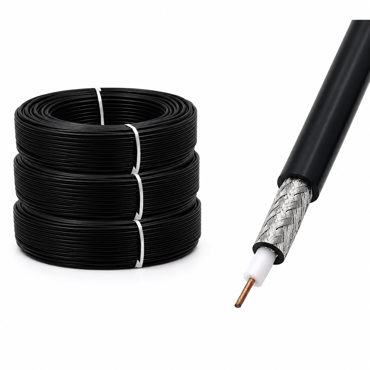
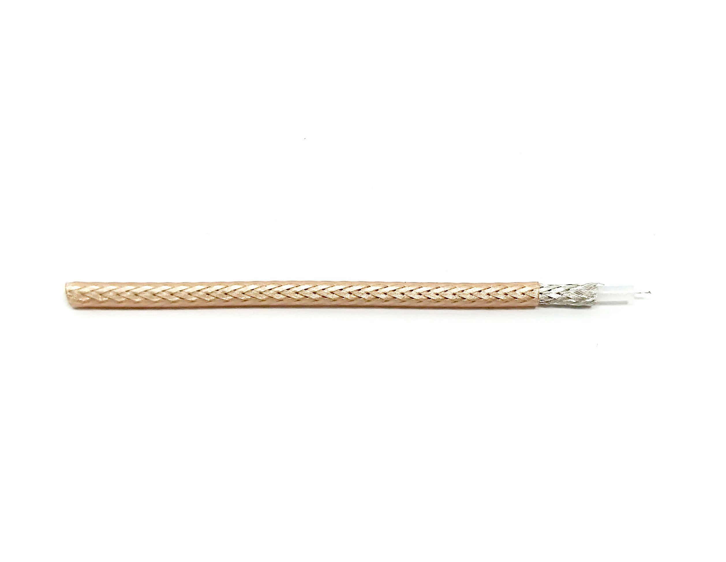
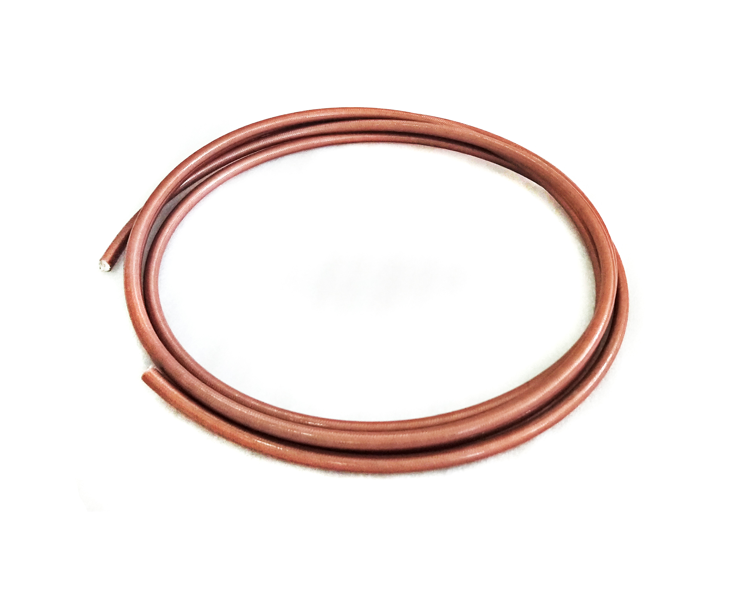
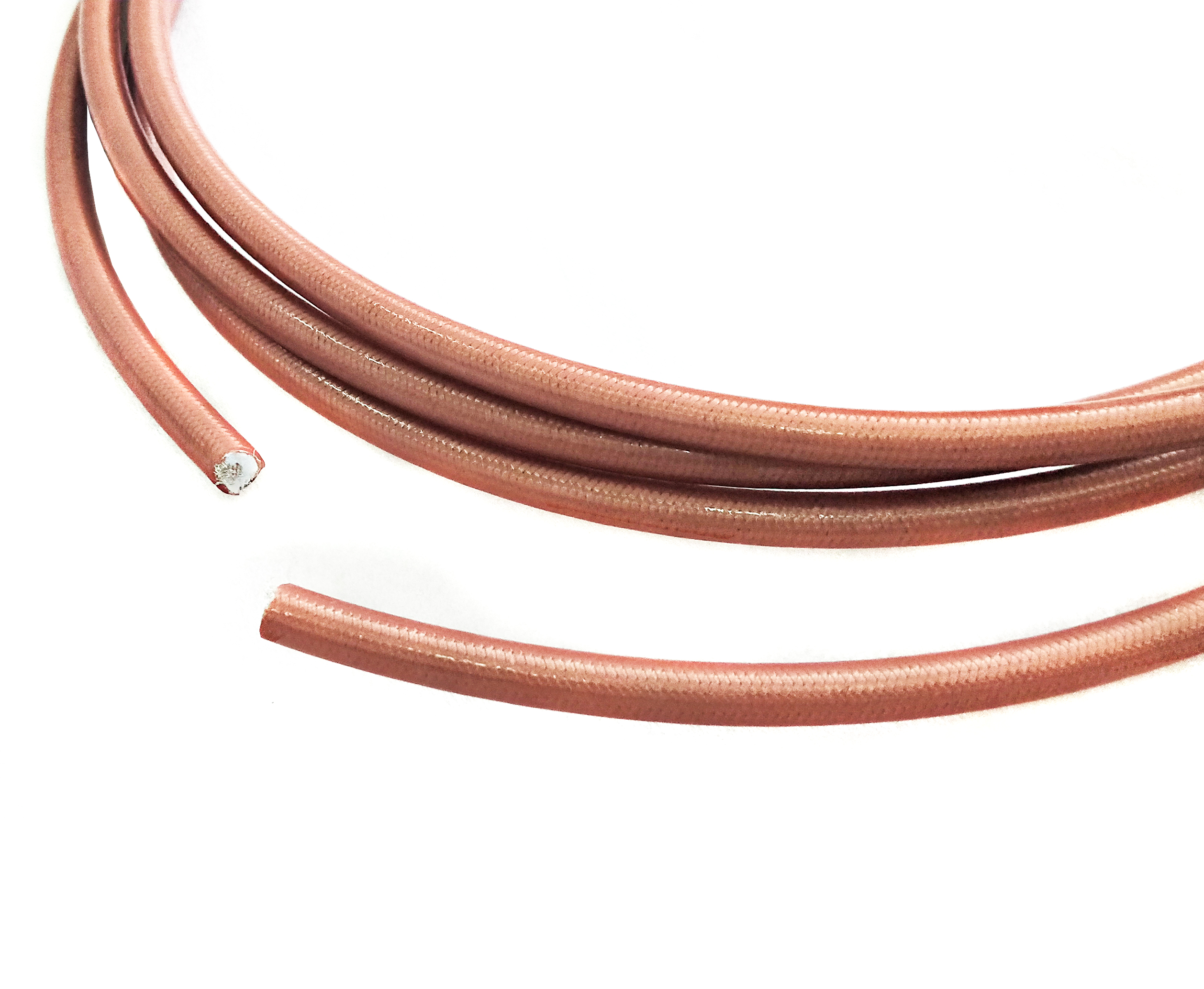
The cable sets the loss, the bend radius and the termination method. These are the families we normally pair with a UHF connector.
Cable family |
Typical use |
1/2 in cable |
Antenna feeders on amateur and land-mobile installations |
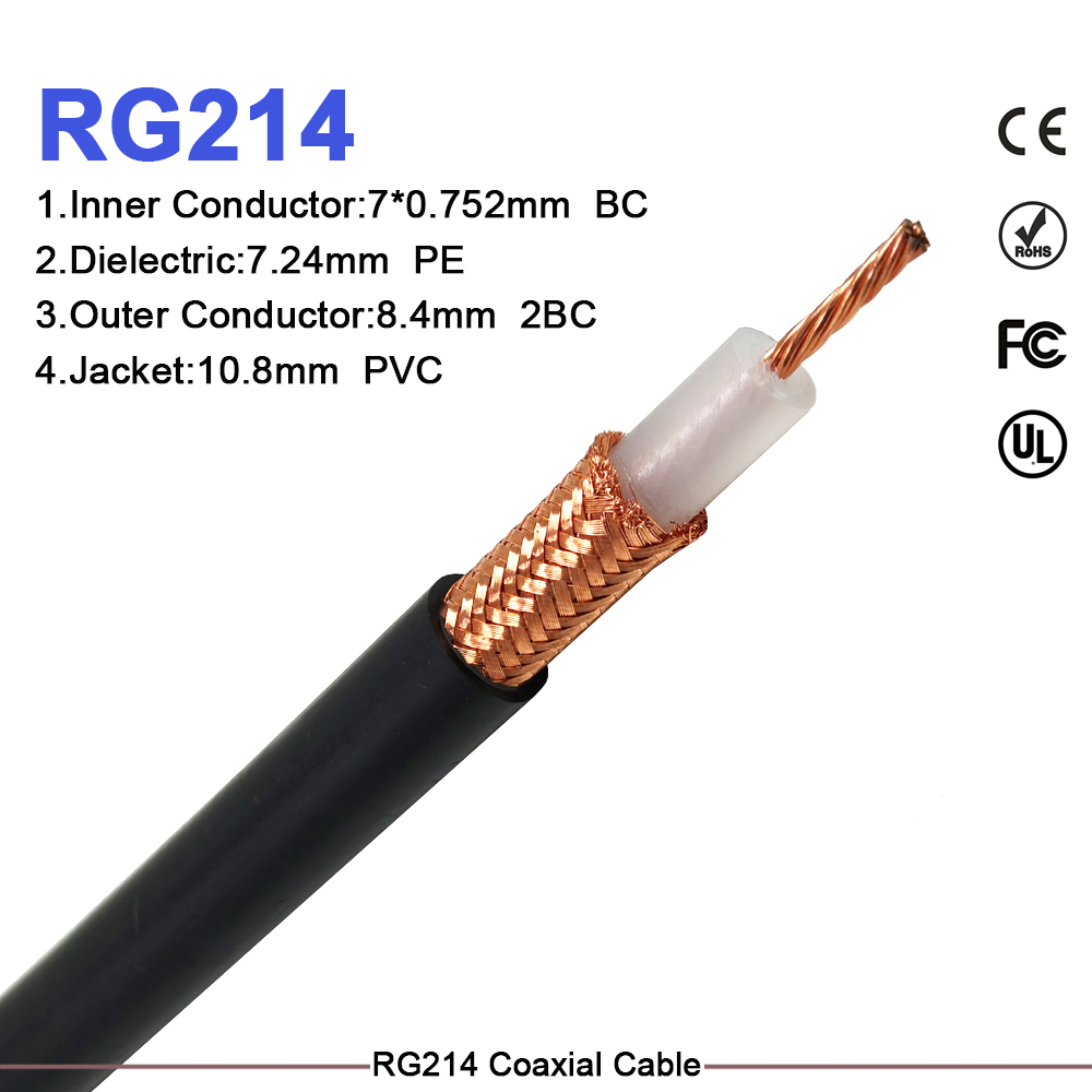
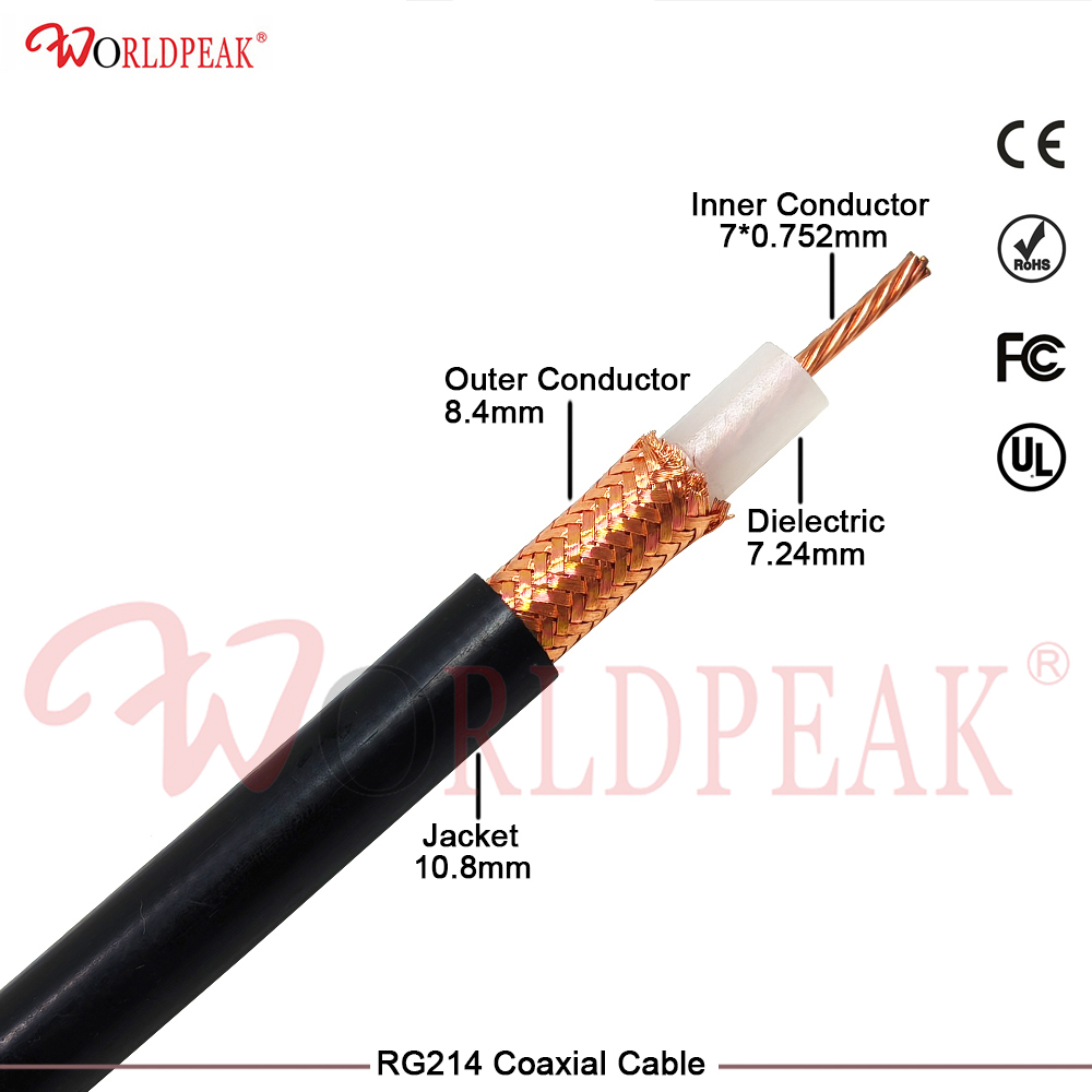
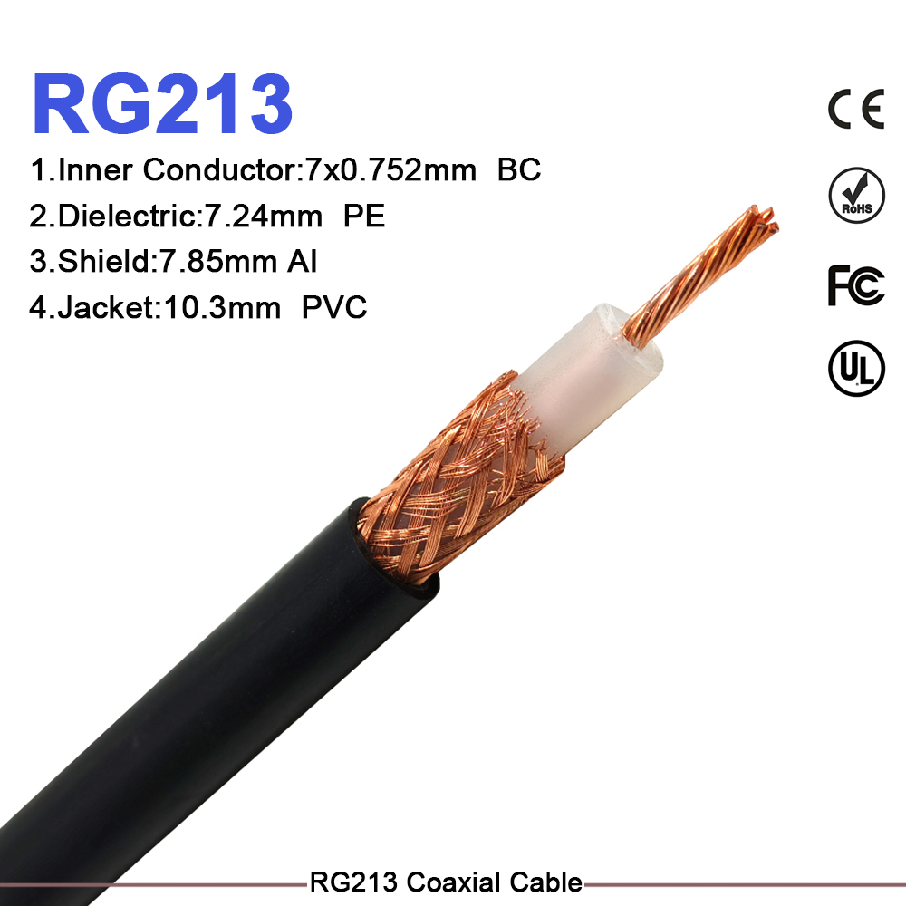
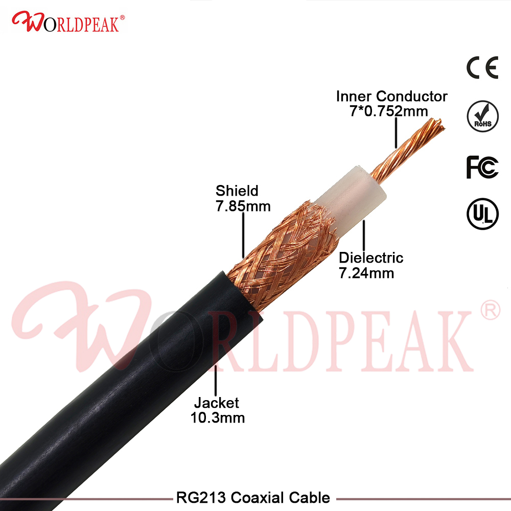
RG8 / RG213 class |
Classic HF and VHF station wiring |
RG58 |
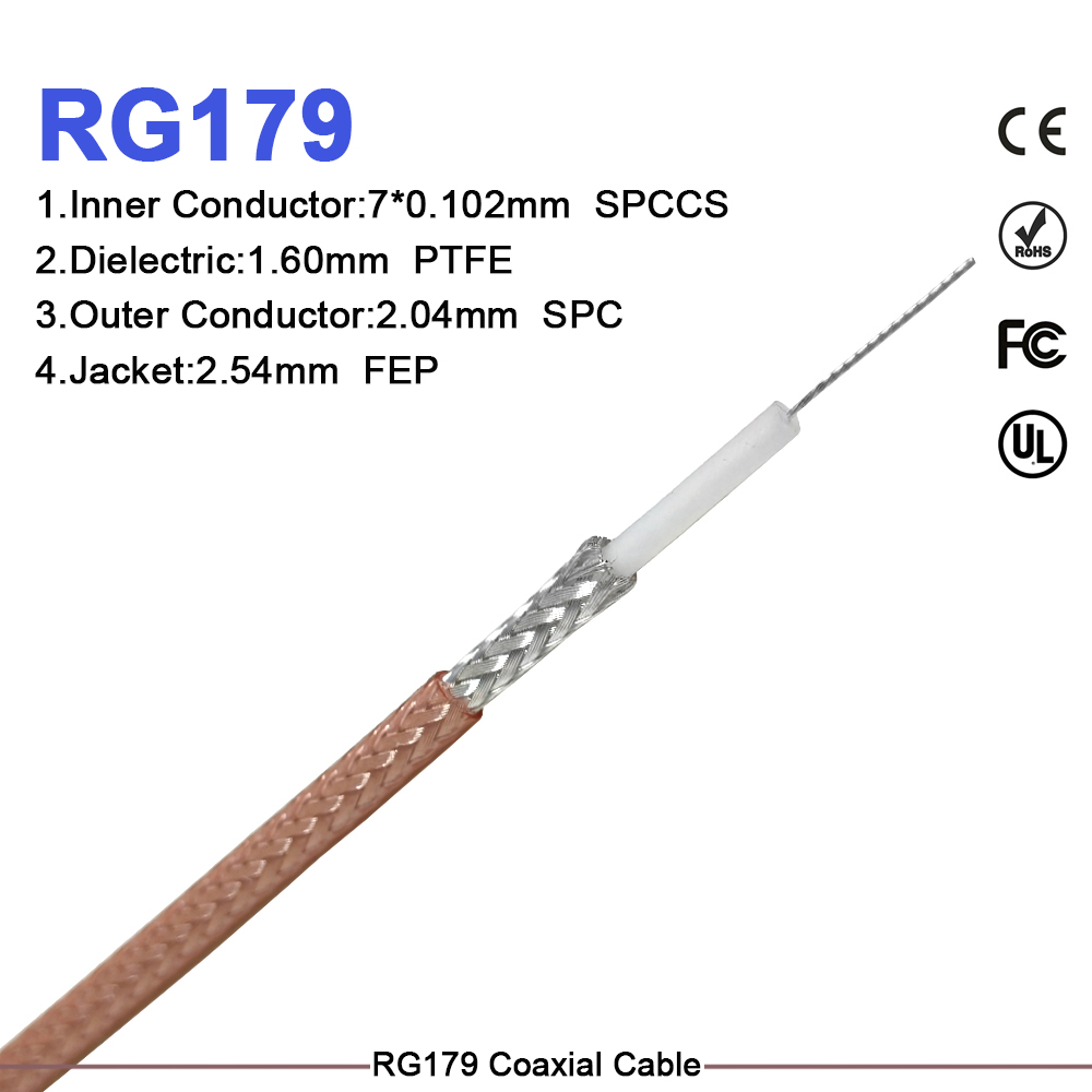
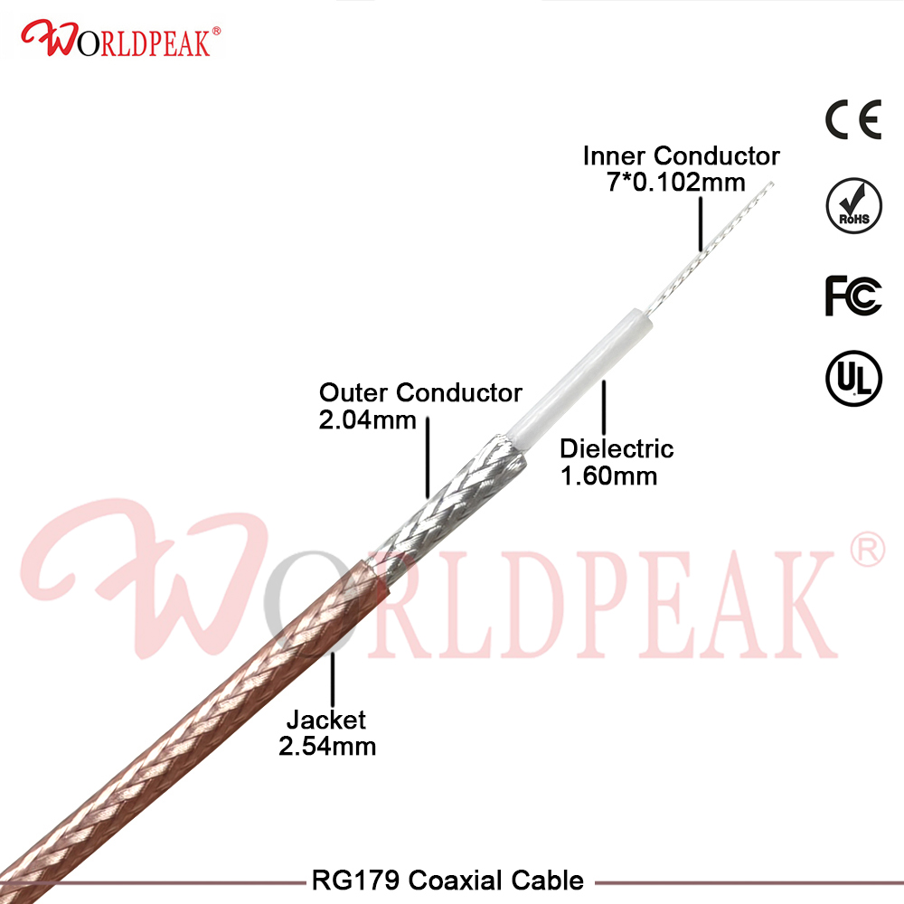
Short flexible leads to transceivers and tuners |
LMR240 |
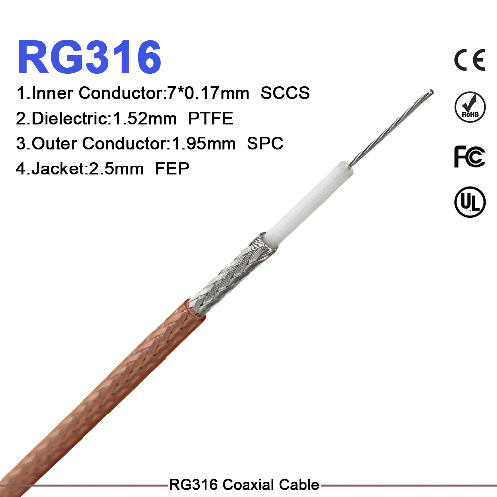
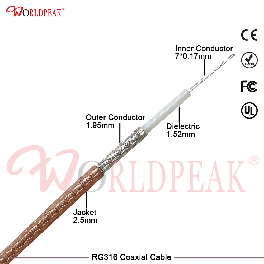
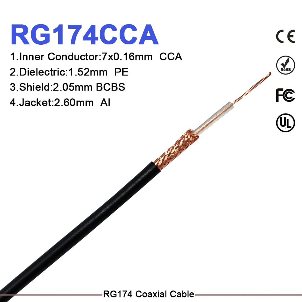
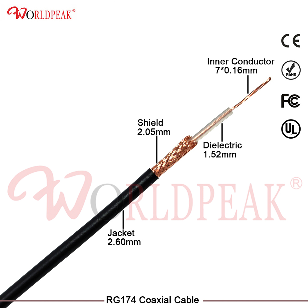
Compact low-loss jumpers where a PL-259 body is needed |
This interface also appears on drawings as PL-259 or SO-239 – same interface, same series. Slash and hyphen spellings are interchangeable throughout our range. Send the drawing as it stands and we will confirm the UHF item against it.
WorldPeak (Zhenjiang WorldPeak Communication Co., Ltd.) builds medium-size coaxial interfaces for outdoor, vehicle and equipment-room work. We make the connector and terminate the cable, so the assembly arrives matched to the cable you already use.
This series is one of 29 we make. The interfaces most often paired with it are BNC, HN type, LC coaxial and SC coaxial.
Q. What does a UHF connector adapt to?
A. 21 interfaces directly and 6 with a condition (a matching pad, a flange chain or a pre-made pigtail). See the matrix above.
Q. Which cable should I use with a UHF connector?
A. Start with 1/2 in - antenna feeders on amateur and land-mobile installations As an alternative, RG8 / RG213 class suits classic HF and VHF station wiring
Q. Why is a UHF connector not used at UHF frequencies?
A. The name is historical. The PL-259 / SO-239 design predates modern UHF work and behaves as a low-frequency interface. Tell us the band and we will confirm suitability.
Send us the two interfaces you need to join, the cable you are using and the frequency band. We will confirm the right UHF part, adapter or assembly and send the specification sheet for that exact part.
Request a quotation or a datasheet - OEM and ODM enquiries welcome.
Email [email protected] WhatsApp +86 139 5140 0893