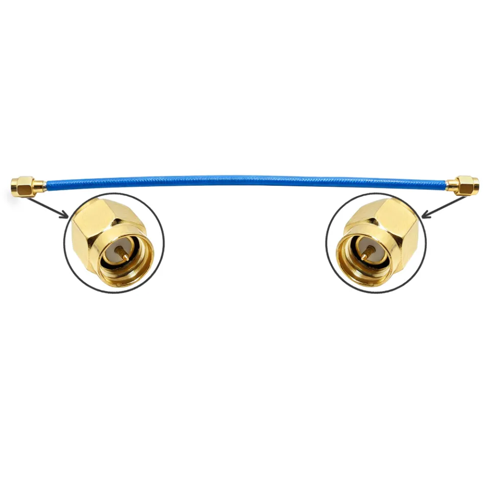
In professional broadcast, surveillance, and telecommunications environments, the BNC male connector remains the definitive quick-connect solution for coaxial signal paths. However, selecting a sub-standard coaxial connector or miscalculating impedance matching can quickly cause signal degradation, structural return loss, and costly downtime in high-frequency applications.
As a specialized manufacturer, WORLDPEAK designs and crafts each BNC connector to withstand demanding industrial stress while keeping signal attenuation at a minimum. This guide walks procurement officers and RF engineers through the technical specifications, physical assembly, and quality verification standards necessary to optimize every RF connector and video connector deployment.
Critical Impedance Matching: 50 Ohm vs. 75 Ohm BNC Male Connectors
A common pitfall during RF system integration is confusing 50 Ohm and 75 Ohm versions of the BNC male connector. Mismatched impedance creates standing waves, leads to high Voltage Standing Wave Ratio (VSWR), and causes reflection loss.
-
50 Ohm BNC Connector: Designed for RF data transmission, wireless communication, two-way radios, and laboratory test instruments. It utilizes a thicker dielectric insulator around the center pin.
-
75 Ohm BNC Connector: Engineered specifically for video signal distribution, HD-SDI broadcast equipment, CCTV camera feeds, and medical monitors. It maintains a consistent 75-ohm impedance across frequencies exceeding 3 GHz to support 4K/8K video transmission.
| Parameter |
50 Ohm BNC Male Connector |
75 Ohm BNC Male Connector |
| Primary Application |
RF / Telecom / Test Equipment |
HD Video / Broadcast / CCTV |
| Frequency Range |
DC to 4 GHz |
DC to 6 GHz (HD-SDI) |
| Dielectric Construction |
Full Teflon / PTFE Insert |
Reduced / Air Dielectric |
| Mating Compatibility |
Mates with 50/75 Ohm female |
Mates with 50/75 Ohm female |
| Typical Cable Types |
RG58, RG142, LMR200 |
RG59, RG6, Belden 1855A |
Mixing a 50 Ohm RF connector with a 75 Ohm coaxial connector path creates an impedance mismatch that severely impacts high-bitrate video streams, introducing ghosting and frame drops. For detailed overall system architectures, refer to the WORLDPEAK Master RF & Video Connector Catalog.
Mechanical Construction and Material Quality Standards
The reliability of a BNC male connector depends directly on the metallurgy and plating specs chosen during manufacturing:
-
Outer Body & Coupling Nut: Precision-machined brass finished with nickel plating provides corrosion resistance, durability against physical impact, and smooth bayonet engagement over 500+ mating cycles.
-
Center Pin: High-grade beryllium copper or brass with minimum 3u gold plating guarantees low contact resistance and long-term oxidation protection.
-
Insulator Material: Premium PTFE (Teflon) offers exceptional thermal tolerance (-55 deg C to +165 deg C) and stable dielectric constants, far outperforming low-cost POM or nylon alternatives.
Step-by-Step Termination Protocol: Crimp vs. Compression
Achieving optimal performance with a video connector requires precise physical assembly. Improper stripping or loose crimping introduces moisture ingress and impedance spikes.
Stripping Preparation -> Insert Dielectric -> Crimp Pin -> Secure Ferrule -> VSWR Inspection
-
Step 1: Precision Cable Preparation: Use a dual-blade coaxial stripper to expose the inner conductor, dielectric, and outer braid to exact manufacturer tolerances.
-
Step 2: Center Pin Termination: Solder or crimp the male contact pin onto the copper core. Ensure no stray shield wire strands contact the center conductor to prevent short circuits.
-
Step 3: Ferrule Crimp: Position the connector body onto the prepared coax, ensuring the dielectric rests flush against the internal stop. Hex-crimp the ferrule using calibrated ratcheting crimp tools.
WORLDPEAK Factory Testing and Quality Control
To guarantee zero-defect delivery for mass production orders, WORLDPEAK subjects every BNC male connector production batch to stringent quality assurance checks:
表格
| Inspection Phase |
Test Equipment |
Standard Criteria |
| Electrical Performance |
Vector Network Analyzer (VNA) |
VSWR < 1.15 @ 3 GHz; Insertion < 0.2dB |
| Mechanical Integrity |
Pull-Force Tester |
Retention Strength > 220 N |
| Environmental Endurance |
Salt Spray Test Chamber |
48-Hour Corrosion-Free Pass |
| Contact Resistance |
Micro-Ohm Meter |
Center Pin Contact < 1.5 mOhm |
Every RF connector dispatched from our ISO9001-certified facility complies with RoHS and REACH environmental guidelines, ensuring seamless integration into global OEM projects.
BNC Male Troubleshooting & Field Maintenance
Even high-grade coaxial connector units can suffer performance drops if poorly handled in the field. Below are common field failure modes and how to resolve them:
-
Intermittent Signal Loss: Usually caused by an improperly crimped center contact pin. Inspect pin depth with a dial gauge to ensure it locks securely inside the front insulator body.
-
High Reflection / Poor VSWR: Frequently caused by bent outer braid wires inside the connector body or using an incorrect hex crimp die size.
-
Bayonet Slop or Loose Locking: Indicates worn spring washers inside the BNC male connector coupling nut. Replace sub-standard connectors with high-durability units rated for 500+ mating cycles.
By pairing the correct 50 Ohm or 75 Ohm BNC connector with professional assembly tools and strict inspection workflows, broadcast operators and telecommunications engineers can guarantee long-term signal integrity across their network. For custom OEM cable assemblies, low MOQ requirements, and wholesale inquiries, contact the engineering support team atWORLDPEAK.
 EN