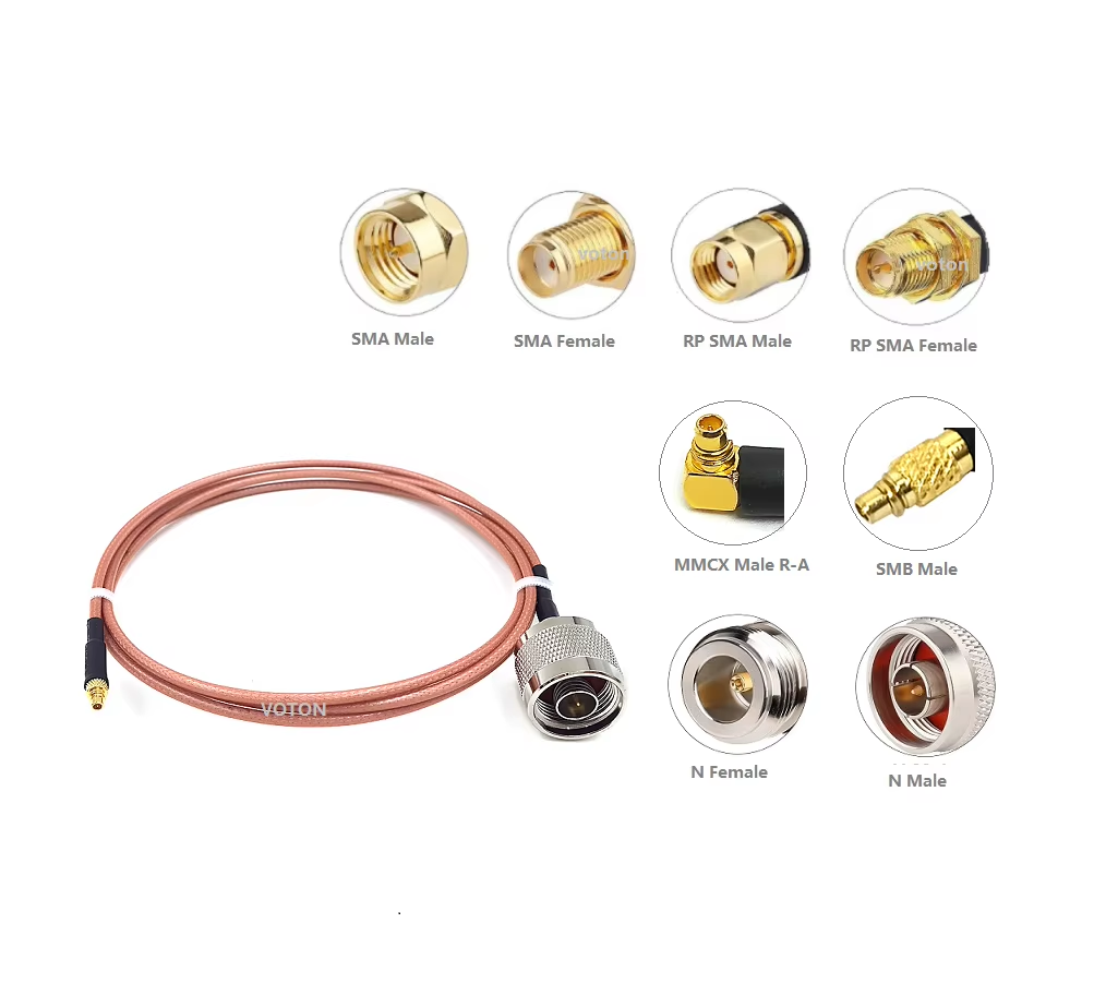
Selecting the right RF cable connector type represents one of the most critical decisions during wireless system architecture and hardware layout. An RF connector serves as more than a simple mechanical joint; it functions as an impedance-matched transmission path that determines maximum operating bandwidth, power handling capability, and structural reliability. Choosing an improper component leads to reflection loss, signal distortion, or electrical breakdown under high RF power levels.
With dozens of RF cable connector types available on the market—ranging from everyday SMA components to high-frequency millimeter-wave options like the 2.4 mm RF connector—matching the right interface to specific operating environments requires careful evaluation. Understanding the core trade-offs across common connector families helps hardware designers optimize system efficiency and prevent signal loss.
Comparing Common Connector Families and Specifications
Each coaxial connector family meets specific frequency range connector limits, power handling requirements, and packaging constraints. Analyzing an SMA BNC N-type comparison alongside high-frequency millimeter-wave designs highlights distinct performance boundaries across different operating frequencies.
-
The SubMiniature Version A (SMA) Family: Standard SMA connectors rely on a threaded coupling mechanism (1/4-36 UNS) and deliver stable 50-ohm performance from DC to 18 GHz. Precision SMA variants extend bandwidth up to 26.5 GHz. With compact physical dimensions and a moderate RF connector power rating of roughly 100 W at 1 GHz, SMA interfaces remain standard across internal PCB modules, wireless routers, and benchtop test leads.
-
The Bayonet Neill-Concelman (BNC) Family: BNC connectors use a twist-and-snap bayonet lock designed for quick coupling without tools. Operating primarily from DC to 4 GHz in standard 50-ohm versions, BNC connectors excel in video transmission, lab oscilloscopes, and low-frequency signal testing. However, the mechanical tolerance of the bayonet mechanism creates impedance variations above 4 GHz, limiting high-frequency microwave utility.
-
The Type N Family: Developed for rugged applications, the N-type connector uses a 5/8-24 threaded coupling mechanism with internal air dielectrics. Rated up to 11 GHz in standard versions and 18 GHz in precision designs, N-type connectors provide a substantial RF connector power rating of up to 300 W at 1 GHz, making them ideal for cellular base station feeds and outdoor antenna installations.
-
The Threaded Neill-Concelman (TNC) Family: Structurally similar to the BNC interface, the TNC connector replaces the quick-release bayonet with a 5/8-24 thread. This change eliminates mechanical vibration bounce and extends the frequency range connector ceiling up to 11 GHz, with a power handling rating around 200 W at 1 GHz.
-
Millimeter-Wave Precision Connectors: When operating frequencies push into microwave and 5G bands, specialized interface dimensions become necessary. The precision 2.4 mm RF connector operates cleanly up to 50 GHz by using air dielectrics and shortened center conductors. Further up the spectrum, 1.85 mm connectors support up to 67 GHz, while 1.0 mm connectors reach 110 GHz for advanced research and sub-terahertz testing.
Detailed Interface Comparison Table
Evaluating key specifications across different RF cable connector types helps clarify trade-offs between physical size, power capabilities, and frequency headroom.
| Connector Type |
Frequency Range Connector Limit |
RF Connector Power Rating (at 1 GHz) |
Characteristic Impedance |
Coupling Mechanism |
| SMA |
DC – 18 GHz (26.5 GHz Precision) |
~100 W |
50 Ohm |
Threaded 1/4-36 |
| BNC |
DC – 4 GHz |
~100 W |
50 Ohm / 75 Ohm |
Bayonet |
| N-Type |
DC – 11 GHz (18 GHz Precision) |
~300 W |
50 Ohm |
Threaded 5/8-24 |
| TNC |
DC – 11 GHz |
~200 W |
50 Ohm |
Threaded 5/8-24 |
| 7-16 DIN |
DC – 7.5 GHz |
~1000 W+ |
50 Ohm |
Heavy Threaded M29x1.5 |
| 2.4 mm RF Connector |
DC – 50 GHz |
~10 W |
50 Ohm |
Precision Threaded M7 |
| MCX / MMCX |
DC – 6 GHz |
~5 W – 10 W |
50 Ohm |
Snap-on |
Application-Specific Selection Logic
Choosing between various RF cable connector types requires matching the physical and electrical parameters of the connector to system demands.
-
High-Power Base Stations and Broadcast Systems: Applications handling power levels past several hundred watts demand robust center contacts and large outer conductors to dissipate heat. While an SMA BNC N-type comparison shows N-type connectors handling up to 300 W, high-power telecom installations often upgrade to 7-16 DIN or 4.3-10 interfaces to handle 1000 W+ continuous power while maintaining low passive intermodulation (PIM) levels.
-
Precision Test and Measurement Equipment: Vector network analyzers, spectrum analyzers, and high-speed digital test rigs require pristine signal paths with low reflection. Standard benchtop setups up to 18 GHz rely on SMA interfaces, whereas high-frequency 5G millimeter-wave testing requires a precision 2.4 mm RF connector. The air-dielectric structure inside a 2.4 mm RF connector ensures VSWR levels remain below 1.15:1 up to 50 GHz.
-
Space-Constrained Mobile and IoT Devices: Compact wireless designs cannot accommodate heavy N-type or 7-16 DIN hardware. Small form-factor snap-on designs like MCX, MMCX, or micro-coax pigtails provide necessary PCB space savings while maintaining a stable 50-ohm impedance up to 6 GHz.
Environmental and Mechanical Trade-Offs
Beyond frequency and power metrics, real-world deployment conditions heavily dictate hardware choices:
-
Vibration and Mechanical Shock: In airborne avionics, vehicle mobile units, and defense systems, constant mechanical vibration can loosen snap-on or bayonet fittings, causing phase jitter and signal dropouts. Threaded designs like TNC, SMA, and N-type connectors lock mating planes together under constant tension to maintain consistent contact pressure.
-
Weather Sealing and Corrosion: Outdoor antenna feeds on towers and rooftops face rain, humidity, and extreme temperature cycling. N-type and TNC connectors offer larger internal silicone O-rings that prevent moisture ingress better than small SMA assemblies. Combining nickel-plated brass or passivated stainless steel housings with gold-plated pin contacts ensures long-term corrosion resistance.
Manufacturing Excellence and Quality Assurance
Producing high-frequency precision hardware like a 2.4 mm RF connector or low-PIM N-type assembly requires ultra-precise CNC machining and strict quality control. Minor air gap variations or pin misalignments can cause impedance discontinuities and degrade performance at high frequencies.
Specialized coaxial manufacturers like WORLDPEAK support global infrastructure deployments with a broad portfolio of custom RF cable connector types. Utilizing advanced multi-axis CNC machining, automated plating, and complete vector network analyzer testing infrastructure, WORLDPEAK delivers precision-engineered SMA, BNC, N-type, TNC, and 2.4 mm RF connector assemblies tailored to exact customer specifications. Adhering to strict international ISO quality management standards, WORLDPEAK supplies reliable coaxial interconnect solutions to telecommunications, broadcast, defense, and test instrumentation industries worldwide.

 EN