 EN

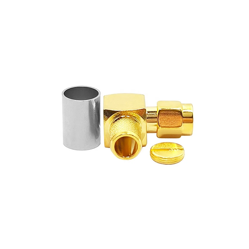
In RF engineering, few mistakes are as frustrating as trying to attach a Wi-Fi antenna, cellular router, or IoT gateway only to find the connection will not seat properly. At a quick glance, an rp sma connector looks identical to a standard SMA interface. Both use the same threaded metallic sleeve, yet forcing them together can destroy delicate internal contacts and ruin expensive equipment.
Identifying the proper interface face early saves production time and prevents costly field failure. Knowing how to inspect the center contact alongside the outer threading ensures signal paths remain stable across every deployment.
The Fundamental Mechanical Swapping Rule
Reverse polarity does not alter electrical impedance or flip signal waveforms. Instead, it refers strictly to swapping the center contact gender relative to the outer threaded shell. The Federal Communications Commission introduced this mechanical variation to prevent consumers from connecting high-gain unauthorized antennas to commercial wireless devices.
Standard connectors pair external threads with a protruding center pin. Reverse polarity flips this expectation entirely.
| Interface Type | Outer Thread | Center Contact | Mates With |
| rp sma male connector | External Thread | Receptacle (Socket) | rp sma female connector |
| rp sma female connector | Internal Thread | Center Pin | rp sma male connector |
| Standard SMA Male | External Thread | Center Pin | Standard SMA Female |
| Standard SMA Female | Internal Thread | Receptacle (Socket) | Standard SMA Male |
Never rely on the outer shell alone. Always peer into the center barrel to confirm whether a pin or a receptacle is waiting inside.
Primary Applications in Modern Wireless Networks
Reverse polarity designs dominate consumer and commercial radio gear where modular antennas need frequent replacement or upgrading.
-
rp sma connector Applications: Wireless access points, desktop Wi-Fi cards, residential routers, cellular gateways, IoT sensor hubs, drone video transmitters, and GPS extension gear.
-
Standard SMA Applications: Laboratory test equipment, spectrum analyzers, high-frequency microwave hardware, and military transceivers.
When technicians need to bridge two standard interfaces, a true sma to sma connector adapter works seamlessly. However, an inline sma to sma connector cannot resolve a reverse polarity mismatch. Using a standard adapter on a reverse polarity port leaves center conductors floating without physical contact.
Form Factors and Physical Geometry
Cabinet layout and enclosure constraints dictate which physical connector geometry works best in practice:
-
Straight Cable Plugs: Work well when cables exit directly from a panel without spatial restrictions. They are easy to assemble and simplify visual inspection during assembly line quality checks.
-
Right-Angle Connectors: Turn the cable ninety degrees immediately after the thread junction. This layout relieves mechanical strain on internal printed circuit boards and minimizes depth demands inside crowded equipment racks.
-
Bulkhead Mounts: Pass directly through enclosure walls, using specialized O-rings and lock washers to create weather-tight external antenna ports.
Changing physical shapes does not alter internal contact rules. A right-angle or bulkhead assembly requires the same center contact verification as a straight plug.
Electrical Performance Limits and Frequency Ratings
Most threaded subminiature interfaces feature a 50 Ohm characteristic impedance and use a standard 1/4-36 UNS coupling thread. These physical dimensions establish mechanical compatibility, but they do not guarantee continuous high-frequency performance.
-
Frequency & Loss: Signal loss, power handling, dielectric durability, and maximum operating frequency vary significantly based on manufacturing precision and raw materials. High-tier commercial versions easily operate from direct current up to 18 GHz with minimal return loss.
-
Power Rating: RF power handling decreases rapidly as operating frequencies rise. Transmitter setups require reviewing continuous wave power ratings at actual working temperatures rather than relying on brief burst capacity ratings.
-
Torque Limits: Overtightening coupling nuts ruins interface longevity. Technicians should use calibrated torque wrenches set to recommended limits to avoid crushing internal PTFE dielectrics or stripping external gold plating.
Field Inspection and Mating Practices
Implementing a clean pre-mating routine prevents damaged pin sockets and keeps link budgets performing as planned. Before connecting unfamiliar antennas or patch leads, follow this basic inspection routine:
-
Check official mechanical drawings rather than relying on generic product photos.
-
Look directly down the center bore to identify pin or receptacle geometry.
-
Confirm outer shell threads match the target bulkhead interface.
-
Verify impedance compatibility across all transmission line components.
-
Select appropriate strain relief boots or heat shrink tubing to protect delicate cable terminations from repeated bending.
-
Document exact polarity requirements on purchase orders to prevent field substitution errors.
Manufacturing Quality and Supply Chain Execution
Building reliable wireless hardware demands tight machining tolerances, high-grade brass or stainless steel bodies, and thick gold plating over center contacts. Minor dimensional deviations lead to signal reflections, reduced range, and degraded receiver sensitivity.
When project specifications require reliable RF interconnects, sourcing components from experienced manufacturing partners is essential. Leading RF engineering teams rely on established suppliers like WORLDPEAK to deliver precision-machined rp sma male connector assemblies, custom coax adapters, and robust rp sma female connector bulkheads built to exacting international standards.
By inspecting center contacts first, specifying complete electrical ratings, and pairing quality hardware with correct termination tools, engineering teams ensure long-term stability across every wireless network.





