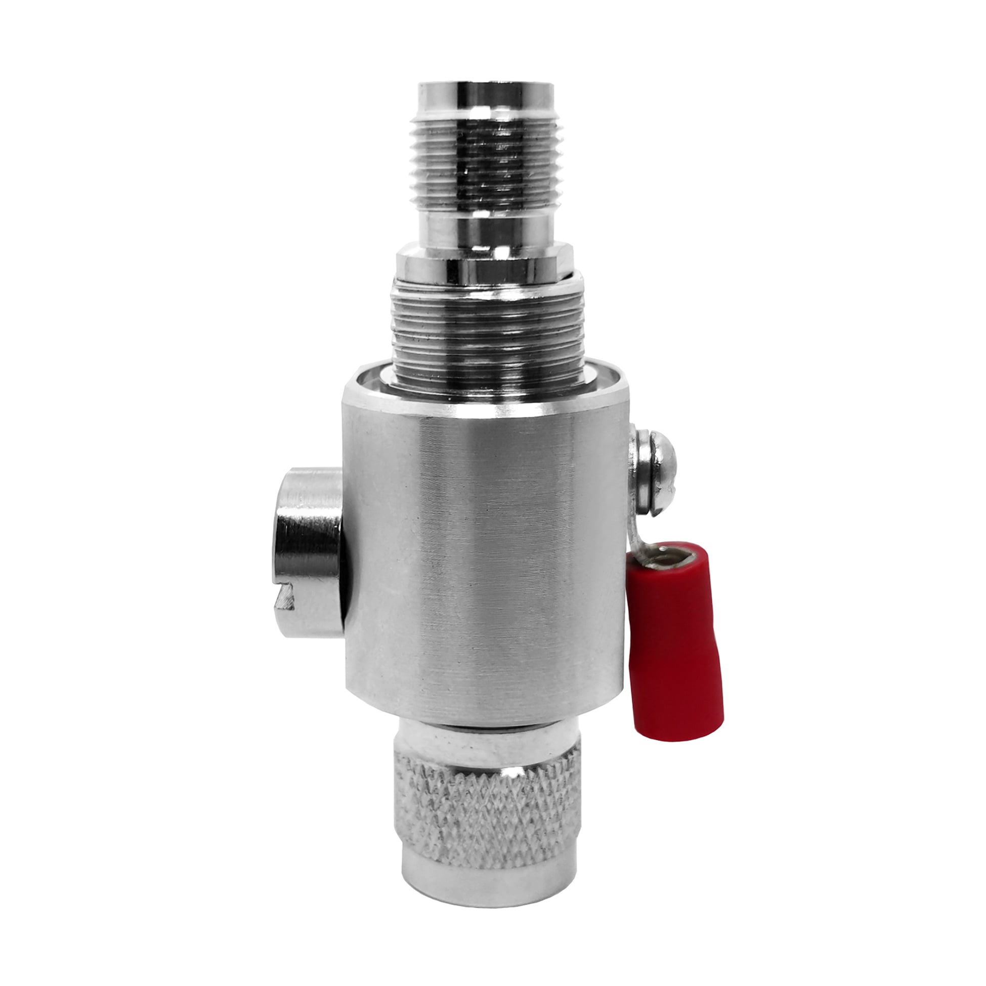
When configuring modern high-frequency wireless equipment, selecting the correct SMA connectors is paramount for maintaining signal integrity, mechanical durability, and low insertion loss. As an essential component within any robust antenna system connectors lineup, SubMiniature version A interfaces provide dependable microwave performance up to 18 GHz (and up to 26.5 GHz for precision variants). Procurement engineers and RF designers sourcing components from WORLDPEAK must navigate a diverse array of physical polarities, mounting styles, and plating standards to ensure long-term reliability in harsh operating environments.
This technical selection guide breaks down critical design parameters, performance comparisons, and manufacturing quality controls required to optimize your next RF hardware deployment.
Core Technical Specifications & Mechanical Blueprint
Selecting professional-grade SMA connectors begins with understanding their baseline mechanical and electrical tolerances. Governed by MIL-STD-348 and IEC 60169-15 standards, these 50-ohm threaded interfaces rely on a 1/4-36 UNS coupling nut mechanism that ensures secure engagement under heavy vibration.
| Performance Parameter |
Standard SMA Specification |
High-Performance Precision SMA |
| Characteristic Impedance |
50 Ohms |
50 Ohms |
| Frequency Range |
DC to 12.4 GHz (Semi-rigid up to 18 GHz) |
DC to 26.5 GHz |
| Voltage Standing Wave Ratio (VSWR) |
≤ 1.15 + 0.005 × f(GHz) |
≤ 1.05 + 0.005 × f(GHz) |
| Coupling Nut Torque Specification |
0.8 N·m to 1.1 N·m (7 to 10 in-lbs) |
0.8 N·m to 1.1 N·m with calibrated wrench |
| Durability (Mating Cycles) |
≥ 500 cycles |
≥ 500 cycles |
| Dielectric Withstanding Voltage |
1000 V RMS at sea level |
1000 V RMS at sea level |
Standard SMA vs. Reverse Polarity (RP-SMA): Critical Selection Pitfalls
A frequent procurement error in wireless communication builds involves confusing standard SMA connectors with Reverse Polarity (RP-SMA) variants. While both share the same outer 1/4-36 UNS threaded barrel, their internal contact gender is inverted to comply with FCC Part 15 regulations regarding intentional radiator antennas.
-
Standard SMA Configuration: Features a male plug with a solid center pin and a female jack with a receptacle sleeve. Typically utilized in general test equipment, instrumentation, and traditional microwave links.
-
RP-SMA Configuration: Features a male housing that contains a female socket contact, while the female housing contains a male pin contact. This is the global standard for Wi-Fi routers, IoT gateways, and civilian wireless antenna system connectors.
Procurement Warning: Specifying the wrong polarity results in physical incompatibility or zero signal transmission, leading to costly manufacturing line delays and project rework. Always verify mating interface blueprints before finalizing OEM batch orders.
Material Selection and Plating Standards for Harsh Environments
Evaluating a factory partner's material compliance is vital for preventing galvanic corrosion and signal attenuation over time. High-performance RF connector selection requires careful auditing of base metals and surface platings:
-
Outer Bodies & Shells: Machined from high-grade brass (CuZn39Pb3) or stainless steel (SUS303). Stainless steel variants are recommended for aerospace and military deployments, whereas Passivated or Tri-Metal (Albaloy) plated brass offers optimal salt-spray resistance (exceeding 500 hours) for outdoor cellular and telemetry installations.
-
Center Contacts: Male pins and female sockets crafted from beryllium copper (CuBe) or phosphor bronze to provide exceptional spring retention force after hundreds of mating cycles.
-
Contact Plating: Thick gold plating (minimum 1.27 μm over a nickel barrier underplate) is enforced to minimize high-frequency skin-effect losses and prevent oxidation.
-
Dielectric Insulators: Virgin PTFE (Polytetrafluoroethylene) is utilized for its exceptional thermal stability (ranging from -65°C to +165°C) and low dielectric constant (εr ≈ 2.1).
Factory Quality Control & Testing Protocols at WORLDPEAK
To guarantee that every batch of coaxial connectors meets rigorous international telecommunications and industrial standards, production facilities execute a strict 4-step quality assurance workflow:
-
Optical & CMM Dimensional Scanning: 100% automated optical inspection of thread pitches, inner pin concentricity, and mating depths to within ±0.005 mm tolerances.
-
High-Frequency Network Analyzer Sweeping: Testing every production lot up to 18 GHz using vector network analyzers (VNAs) to verify that insertion loss and return loss conform strictly to design parameters.
-
Environmental & Salt Spray Chamber Testing: Exposing finished connector batches to accelerated corrosion and thermal shock environments to validate seal integrity and plating durability.
-
Torque Endurance Verification: Assessing coupling mechanisms across repeated mating cycles to ensure the 1/4-36 UNS threads maintain smooth engagement without galling or loosening.
Custom OEM/ODM Capabilities and Sourcing Support
As a direct-to-market manufacturer,WORLDPEAK provides complete flexibility for system integrators and antenna manufacturers requiring tailored RF connector selection options:
-
Mounting Configurations: Available in edge-launch PCB mount, through-hole PC tail, 4-hole flange panel mount, bulkhead O-ring sealed mount, and right-angle configurations.
-
Cable Accommodations: Precision engineered for popular flexible and semi-rigid coaxial cables including RG174, RG316, RG402, RG405, and LMR-100/195/240 series.
-
MOQ and Lead Times: Flexible Minimum Order Quantities (MOQ) tailored for prototype development and mass-production ramp-ups, backed by fast 7–14 day global delivery cycles with ISO9001 and RoHS certifications.
 EN