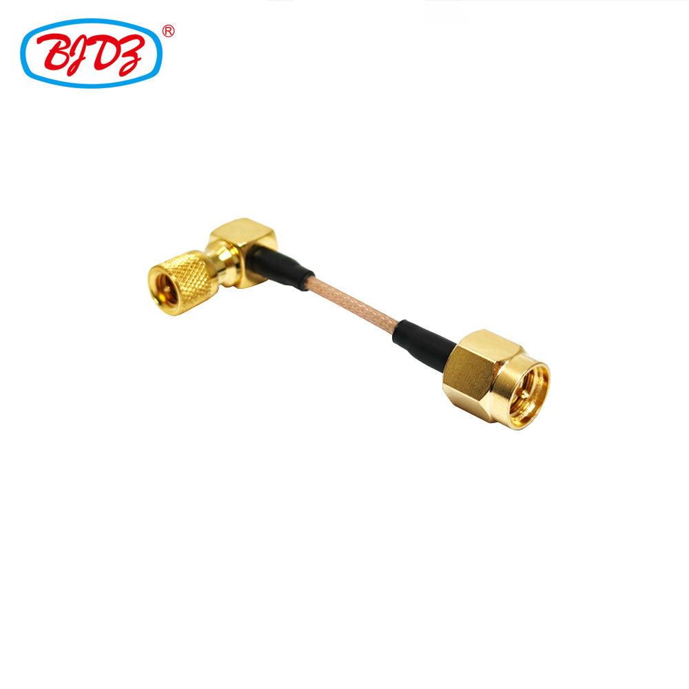
Radio frequency and microwave systems depend heavily on high-integrity signal pathways to function accurately. Among the vast array of interconnects used in modern electronics, the SMA to SMA RF cable stands as a cornerstone across laboratory testing environments, wireless telecom infrastructure, aerospace electronics, and compact microwave modules. Its subminiature threaded coupling interface offers a rare balance of high frequency performance, reliable mechanical retention, and compact physical dimensions.
Navigating the selection process for an optimal SMA cable assembly requires evaluating far more than just matching interface genders. Factors such as operating frequency range, conductor geometry, phase stability under movement, dielectric loss, and thermal durability directly govern whether a test setup or embedded sub-system delivers repeatable results. Selecting the wrong coaxial cable type or connector configuration can introduce unwanted impedance mismatches, signal distortion, or thermal failure under high power levels.
Evaluating Coaxial Cable Types for SMA Assemblies
Matching the coaxial cable construction to your operating band and mechanical installation environment forms the foundation of a reliable signal path. Standard coax options range from flexible braided lines to rigid and semi-rigid configurations, each presenting distinct trade-offs between mechanical flexibility, power handling, and attenuation.
| Coaxial Cable Type |
Outer Diameter |
Maximum Frequency |
Attenuation at 6 GHz |
Primary Application |
| RG-316 |
2.50 mm |
3 GHz |
High / Limited at High Freq |
Compact Internal Wiring & Short Jumper Runs |
| RG-142 |
4.95 mm |
12.4 GHz |
~2.5 dB/m |
General Bench Testing & Double-Shielded RF Paths |
| 0.085 Semi-Rigid |
2.16 mm |
18 GHz |
~1.8 dB/m |
Fixed Microwave Enclosures & High-Density Racks |
| 0.141 Semi-Rigid |
3.58 mm |
18 GHz |
~1.2 dB/m |
Precision Instrumentation & Low-Loss RF Paths |
| LMR-100 |
2.54 mm |
6 GHz |
~3.0 dB/m |
Flexible Wireless Antenna Lines & Field Cables |
Flexible options like RG-142 provide excellent double-braided shielding and physical durability, making them popular for general-purpose bench test leads up to 12.4 GHz. When projects require operation up to 18 GHz with minimal attenuation, semi-rigid lines with solid copper outer jackets remain the preferred choice for fixed indoor installations.
Comparing SMA to SMA and SMA to BNC Configurations
Choosing between a straight SMA to SMA RF cable assembly and an SMA to BNC cable comes down to matching the physical connector interfaces while taking system frequency limitations into account.
An SMA to SMA RF cable operates as a dedicated high-frequency interconnect when both source and load modules feature threaded female SMA ports. This direct connection preserves constant 50-ohm impedance through the interface and maintains low reflection coefficients up to 18 GHz or higher depending on the specific connector grade.
In contrast, an SMA to BNC cable bridges the gap between microwave modules and lower-frequency equipment like oscilloscopes, function generators, or legacy monitoring gear. BNC connectors utilize a quick-disconnect bayonet locking mechanism that speeds up bench hookups, but their physical geometry generally limits clean performance to frequencies below 3 GHz to 4 GHz.
For high-frequency production test environments, standardizing all primary transmission lines on precision SMA to SMA RF cable paths and using targeted SMA-to-BNC adapters only at equipment interface points keeps system noise low and signal fidelity high.
Importance of Phase Stability in Phase-Sensitive Measurements
In applications such as phased-array antenna calibration, radar signal processing, beamforming module validation, and complex material characterization, transmission line electrical length must remain rock-solid. Phase drift caused by cable flexing or temperature fluctuations severely compromises measurement accuracy.
Standard flexible coaxial cables tend to undergo structural deformation when bent or twisted, altering the internal distance between the center conductor and outer shield. Under repeated mechanical stress, standard braided cables can exhibit phase shifts exceeding five degrees at 6 GHz after several thousand flex cycles.
A high-performance precision RF cable engineered specifically for phase stability utilizes specialized tape-wrapped PTFE dielectrics and multi-layered shielding. These advanced constructions maintain phase consistency within half a degree under continuous motion, protecting sensitive phase-array measurements against mechanical drift.
Real Field Case: 5G Small Cell Transceiver Validation
During the development and characterization of a 5G small cell mass-production module, engineers faced the challenge of simultaneously evaluating 64 independent transmit paths across the 3.3 GHz to 4.2 GHz frequency spectrum.
To ensure accurate digital beamforming calibration, the test harness required custom SMA jumper leads engineered to tight electrical tolerances: a Voltage Standing Wave Ratio (VSWR) below 1.15:1, total insertion loss under 0.5 dB over a 0.3-meter length, and temperature-induced phase variance under one degree across a 0 to 50°C thermal range.
By adopting 0.141-inch semi-rigid SMA to SMA RF cable assemblies fitted with gold-plated stainless steel bodies and precision pin contacts, the engineering team eliminated cable-induced measurement variations. The tight tolerances enabled precise phase alignment across all 64 channels, accelerating product certification and ensuring seamless volume production.
Understanding Key Installation Mistakes and Prevention Strategies
Achieving maximum performance from a precision SMA cable assembly requires proper handling during assembly, installation, and daily bench testing.
-
Incorrect Mating Torque: Hand-tightening SMA couplings often leaves the connector face partially unseated, creating an impedance discontinuity that causes reflection spikes. Conversely, over-tightening with standard wrenches can deform the delicate center contact pin. Always use a calibrated 8 in-lb (0.9 Nm) torque wrench designed for SMA hardware.
-
Violating Minimum Bend Radius: Forcing a flexible or semi-rigid cable into a turn tighter than its specified minimum bend radius compresses the dielectric insulator. This leads to severe impedance drops, higher insertion loss, and mechanical fatigue over time.
-
Ignoring Interface Cleanliness: Dust, metal fragments, or skin oils on the dielectric mating face or pin contact degrade high-frequency electrical performance. Inspect connector faces with a magnifier and clean contacts using lint-free swabs and isopropyl alcohol before mating.
-
Mating Damaged Pins: Connecting a worn or bent male center pin into a precision female socket can ruin the socket's internal spring fingers, permanently damaging expensive test equipment ports.
Scaling Manufacturing Quality for Critical RF Interconnects
Behind every dependable wireless network, satellite link, and automated test station lies a requirement for consistently manufactured coaxial assemblies. Minor variations in stripping dimensions, improper braid soldering, or variable crimp pressure can cause significant batch-to-batch performance discrepancies.
Worldpeak resolves these critical challenges through automated precision machining, rigorous assembly standards, and complete RF characterization capabilities. Delivering an extensive catalog of SMA to SMA RF cable assemblies, SMA to BNC cable configurations, SMA jumper wires, and precision adapter series, Worldpeak utilizes high-grade materials including stainless steel or brass bodies, heavy gold plating, and premium fluoropolymer dielectrics.
Capable of processing RG-316, RG-142, LMR-100, and semi-rigid cables, Worldpeak subjects every custom cable assembly to 100% automated VSWR and insertion-loss testing across the intended frequency band before dispatch. Whether outfitting microwave test benches, scaling wireless infrastructure deployments, or sourcing specialized high-frequency jumpers, partnering with an established manufacturer like Worldpeak provides the thermal, mechanical, and electrical performance required for mission-critical signal chains.

 EN