 EN

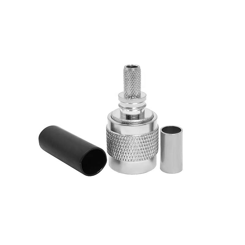
When a high-frequency radio signal performs perfectly on a lab bench but suffers intermittent signal dropouts on a moving vehicle, the physical interface is often the root cause. Coaxial cable connections in mobile, marine, or aerospace environments are exposed to continuous mechanical vibration, thermal expansion, and mechanical shock.
While bayonet-style interfaces allow rapid coupling, they can wobble under severe strain. The tnc connector solves this reliability issue by replacing bayonet pins with a robust threaded coupling mechanism, maintaining a stable 50 Ohm transmission path under harsh field conditions.
Threaded Retention Mechanics versus Bayonet Couplings
The Threaded Neill-Concelman interface was engineered to overcome the physical limitations of bayonet connectors in high-vibration environments. Both families share similar internal dimensions, but their mechanical behavior under load differs significantly.
| Mechanical Feature | TNC RF Connector | BNC Connector |
| Coupling Type | Threaded (7/16-28 UNEF) | Bayonet (Twist & Lock) |
| Vibration Resistance | Excellent (Helps prevent signal micro-flicker) | Moderate (Prone to movement under vibration) |
| Typical Frequency Range | DC to 11 GHz (Extended designs to 18 GHz) | DC to 4 GHz |
| Primary Deployment Environment | Vehicles, avionics, outdoor infrastructure | Test benches, indoor CCTV, laboratory equipment |
The threaded coupling sleeve on a tnc rf connector ensures continuous contact pressure between outer conductors. This tight mechanical contact minimizes passive intermodulation and prevents sudden changes in Voltage Standing Wave Ratio when cables are pulled or shaken.
Physical Form Factors and Mechanical Variations
Selecting the right connector configuration depends heavily on internal cabinet depth, panel thickness, and cable routing constraints.
-
Straight Cable Plugs: Standard choice for direct line-of-sight runs where rear-panel clearance is unrestricted. Straight housings allow uniform cable stripping, easy crimping, and clear visual alignment of internal dielectrics.
-
tnc bulkhead connector Assemblies: Designed to pass high-frequency signals through enclosure walls or weather-tight bulkheads. These receptacles feature outer mounting threads, lock washers, and O-ring grooves to prevent moisture ingress into sealed equipment cabinets.
-
Right-Angle Connectors: Directs the coaxial cable at a 90-degree angle to the panel face, preserving minimum bend radius limits in tight equipment bays and reducing mechanical strain on circuit board joints.
Special attention must be paid when working with reverse-polarity designs. Reverse-polarity connectors swap the center pin and socket contacts while retaining standard outer threads. Mating standard parts with reverse-polarity versions will crush the center conductor or leave the circuit incomplete.
Technical Specifications and Performance Limits
System engineers should evaluate a tnc coax connector as a complete electrical system rather than a standalone mechanical part.
-
Characteristic Impedance: Must be matched precisely to 50 Ohm transmission lines. Mismatched impedance creates immediate RF energy reflections and degrades receiver sensitivity.
-
Frequency and VSWR Limits: Although standard product catalogs list performance through 11 GHz, actual limits depend on cable quality, strip precision, and assembly workmanship.
-
Plating and Contact Material: High-reliability housings feature brass or stainless steel bodies plated with nickel or tri-metal alloys, while center contacts utilize beryllium copper with thick gold plating to resist corrosion.
-
Torque Ratings: Proper coupling torque is critical. Hand-tightening may leave the thread loose under vibration, whereas over-tightening with uncalibrated tools deforms internal PTFE insulators.
International standards such as MIL-STD-348 define interface mating dimensions to guarantee mechanical compatibility across manufacturers. However, physical compatibility alone does not replace complete environmental qualification testing for shock, salt spray, and water ingress.
Assembly and Quality Control Checklist
Achieving reliable high-frequency performance requires disciplined cable preparation and standardized crimp tooling:
-
Strip cable jackets, braid shields, and dielectrics to exact manufacturer dimensions using calibrated coaxial strip tools.
-
Avoid nicking shield strands or scratching center conductors, as surface defects increase high-frequency resistance.
-
Ensure center pins are properly seated before soldering or crimping with ratchet-controlled dies.
-
Verify that outer ferrule crimps encapsulate the shield braid evenly without deforming internal dielectrics.
-
Conduct continuous VSWR sweeps and cable insulation resistance testing prior to field deployment.
Industrial Applications and Supply Chain Excellence
Threaded RF components are essential across industries where system failure is not an option:
-
Avionics and Defense: Connecting cockpit communications, navigation receivers, and radar displays exposed to flight vibration and altitude pressure changes.
-
Transportation and Rail: Housing rooftop cellular and Wi-Fi antennas on high-speed trains and transit buses.
-
Outdoor Telecom Infrastructure: Linking remote radio units, base stations, and wireless backhaul hardware mounted on exposed towers.
When project specifications call for verified low-loss characteristics, precise electrical tolerances, and robust weather sealing, partnering with an experienced manufacturer is vital. Global engineering teams depend on trusted suppliers like WORLDPEAK for high-precision tnc rf connector hardware, specialized tnc bulkhead connector assemblies, and custom coaxial cable runs manufactured to strict international standards.
By matching impedance, verifying mechanical clearances, and implementing controlled assembly techniques, engineers ensure every tnc coax connector delivers clean signal performance over a long service life.





