 EN

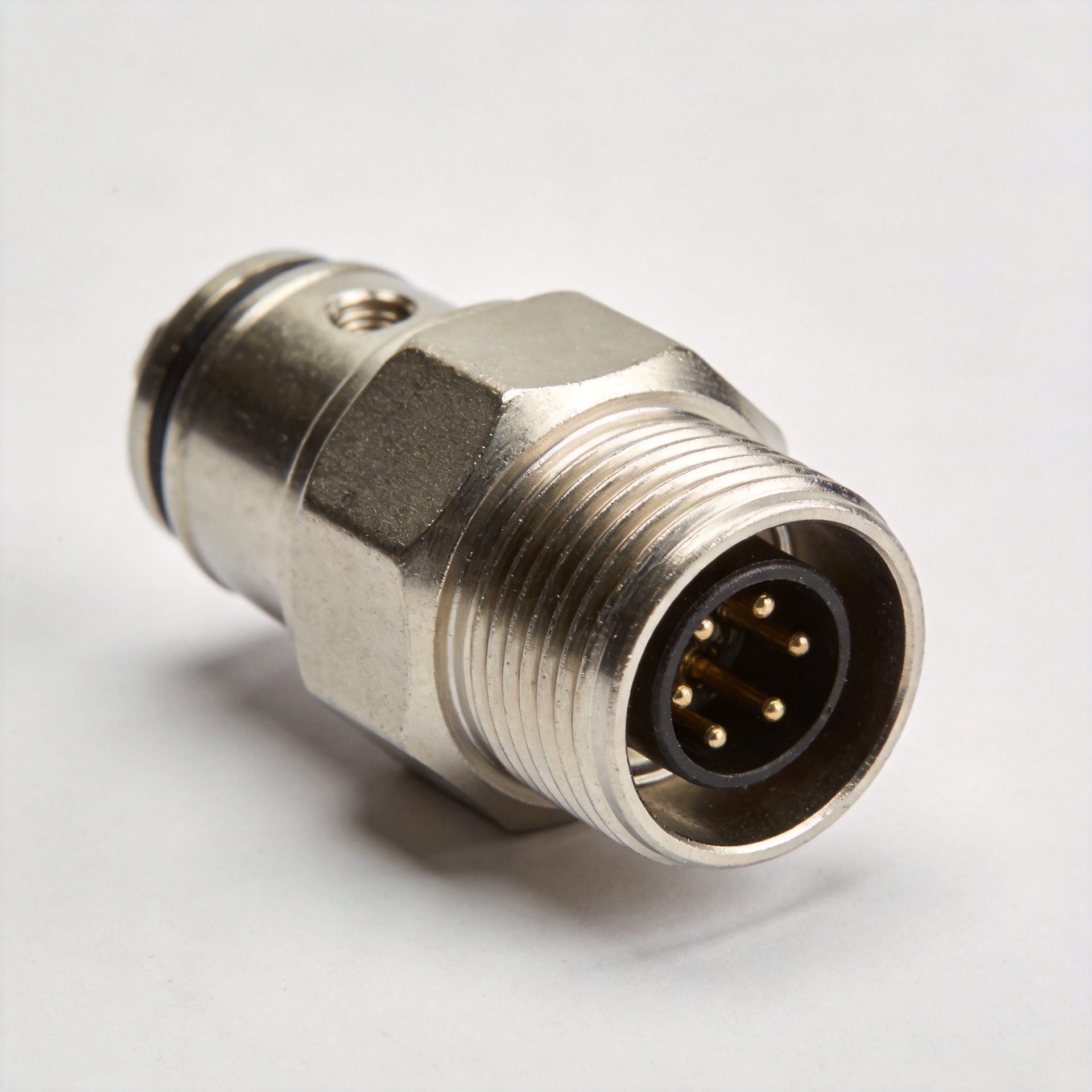
Field failures in high-frequency wireless equipment often trace back to physical connection instability rather than active silicon malfunction. While bayonet-style connectors provide rapid coupling during bench evaluations, mechanical shock and continuous vibration in transport, railway, and outdoor communications frequently induce contact chatter. A precision tnc plug connector resolves this mechanical vulnerability by substituting the quick-twist lug mechanism with a continuous 7/16-28 UNEF threaded coupling nut. This threaded engagement maintains constant axial contact pressure against the outer conductor ground ring, preventing microphonic noise, intermodulation distortion, and accidental disengagement.
In industrial signal routing, system architects frequently contrast the tnc plug connector with other standard interfaces. For example, consumer broadband distribution often relies on a 75-ohm f plug connector for economical television and set-top receiver feeds. However, routing low-noise telemetry or microwave radar feeds through an f plug connector introduces severe impedance mismatch penalties and signal reflection. Selecting a precision 50-ohm tnc plug connector ensures continuous broadband performance up to 11 GHz, with premium stainless-steel variants extending utility through 18 GHz.
Mechanical Architecture and Interface Parameter Matrix
Coaxial connector selection requires analyzing mechanical dimensions, characteristic impedance, coupling torque, and dynamic frequency boundaries. Substituting an f plug connector into an environment requiring an industrial tnc plug connector risks catastrophic link degradation due to structural and dielectric differences. Similarly, confusing an rp tnc male connector with a standard interface leads to immediate mechanical pin collapse.
Parameter Category
Standard TNC Plug Connector
Reverse Polarity (RP) TNC Male Connector
Commercial F Plug Connector
Industrial Bulkhead Receptacle
Mating Thread Specification
7/16-28 UNEF-2B Thread
7/16-28 UNEF-2B Thread
3/8-32 UNEF Thread
7/16-28 UNEF-2A External
Center Contact Architecture
Solid Male Pin Contact
Hollow Female Socket Contact
Exposed Coaxial Center Conductor
Receptive Gold-Plated Socket
Characteristic Impedance
50 Ohm (Optional 75 Ohm)
50 Ohm Nominal
75 Ohm Nominal
50 Ohm Matched
Upper Frequency Cutoff
11 GHz to 18 GHz
6 GHz to 11 GHz
1 GHz to 3 GHz
11 GHz to 18 GHz
Common Application Focus
Radar, Avionics, Base Station
Wi-Fi Gear, Part 15 Antennas
CATV, DOCSIS Cable Modems
Panel Flange, Weatherproof Box
| Parameter Category | Standard TNC Plug Connector | Reverse Polarity (RP) TNC Male Connector | Commercial F Plug Connector | Industrial Bulkhead Receptacle |
|---|---|---|---|---|
| Mating Thread Specification | 7/16-28 UNEF-2B Thread | 7/16-28 UNEF-2B Thread | 3/8-32 UNEF Thread | 7/16-28 UNEF-2A External |
| Center Contact Architecture | Solid Male Pin Contact | Hollow Female Socket Contact | Exposed Coaxial Center Conductor | Receptive Gold-Plated Socket |
| Characteristic Impedance | 50 Ohm (Optional 75 Ohm) | 50 Ohm Nominal | 75 Ohm Nominal | 50 Ohm Matched |
| Upper Frequency Cutoff | 11 GHz to 18 GHz | 6 GHz to 11 GHz | 1 GHz to 3 GHz | 11 GHz to 18 GHz |
| Common Application Focus | Radar, Avionics, Base Station | Wi-Fi Gear, Part 15 Antennas | CATV, DOCSIS Cable Modems | Panel Flange, Weatherproof Box |
Polarity Realities and Contact Pin Mating Rules
A recurring integration error in wireless antenna deployment is the mechanical incompatibility between a standard tnc plug connector and an rp tnc male connector. Under regulatory mandates established by the Federal Communications Commission (FCC Part 15), consumer wireless manufacturers adopted reverse-polarity interfaces to prevent unauthorized high-gain antenna swaps.
An rp tnc male connector utilizes the identical outer threaded shell as a standard tnc plug connector, yet it houses a female contact socket within that male housing. Conversely, an RP female receptacle contains a protruding male pin. When an installer forces a standard tnc plug connector onto an RP female port, two male center pins collide, resulting in bent pins, broken internal dielectrics, and total signal loss. Verifying center contact gender prior to mating prevents field replacement downtime.
Component Identity
Outer Shell Mechanism
Internal Contact Gender
Compatible Mating Receptacle
Primary Deployment Field
Standard TNC Plug Connector
Threaded Outer Nut
Protruding Solid Gold Pin
Standard Female Jack or Bulkhead
Defense, Avionics, Test Racks
RP TNC Male Connector
Threaded Outer Nut
Recessed Spring Basket Socket
RP TNC Female Jack Receptacle
Commercial Wi-Fi, LoRa, Antennas
Utility F Plug Connector
Threaded Hex Nut
Cable Center Solid Copper Core
Female F Barrel Splice Receptacle
Cable Television, Fixed Satellite
TNC Female Bulkhead Connector
Threaded Outer Barrel
Internal Female Spring Contact
Standard TNC Plug Connector
Chassis Feedthrough, Remote Radio
| Component Identity | Outer Shell Mechanism | Internal Contact Gender | Compatible Mating Receptacle | Primary Deployment Field |
|---|---|---|---|---|
| Standard TNC Plug Connector | Threaded Outer Nut | Protruding Solid Gold Pin | Standard Female Jack or Bulkhead | Defense, Avionics, Test Racks |
| RP TNC Male Connector | Threaded Outer Nut | Recessed Spring Basket Socket | RP TNC Female Jack Receptacle | Commercial Wi-Fi, LoRa, Antennas |
| Utility F Plug Connector | Threaded Hex Nut | Cable Center Solid Copper Core | Female F Barrel Splice Receptacle | Cable Television, Fixed Satellite |
| TNC Female Bulkhead Connector | Threaded Outer Barrel | Internal Female Spring Contact | Standard TNC Plug Connector | Chassis Feedthrough, Remote Radio |
Chassis Integration Using TNC Female Bulkhead Connector
Protecting internal receiver circuits against moisture ingress, dust contamination, and electromagnetic leakage requires robust chassis pass-through components. A tnc female bulkhead connector provides a secure transition between external cabling and internal printed circuit boards. Unlike a basic slip-on adapter or an inexpensive f plug connector wall plate, a heavy-duty tnc female bulkhead connector incorporates rear-mount O-rings, silicone sealing gaskets, and precision-machined D-flat profiles. The D-flat mounting hole prevents the connector body from twisting inside the enclosure when an external tnc plug connector is torqued into place.
Integration Requirement
Bulkhead Design Criterion
Technical Failure Mode
Engineering Countermeasure
Environmental Ingress Protection
Integrated Nitrile / Silicone O-Ring
Water seepage through mounting hole
Specify IP67 or IP68 hermetic glass seals
Enclosure Anti-Rotation
Single D-Flat or Double D-Flat Body
Connector spins during external cable torquing
Punch matching D-shaped chassis cutouts
High-Density Panel Clearance
Flange Width vs Hex Nut Clearance
Tool interference preventing proper torque
Utilize narrow-profile rear-tightening nuts
Signal Grounding Continuity
Direct Metal-to-Chassis Contact Face
High RF ground loop impedance and noise
Strip anodization around chassis panel holes
| Integration Requirement | Bulkhead Design Criterion | Technical Failure Mode | Engineering Countermeasure |
|---|---|---|---|
| Environmental Ingress Protection | Integrated Nitrile / Silicone O-Ring | Water seepage through mounting hole | Specify IP67 or IP68 hermetic glass seals |
| Enclosure Anti-Rotation | Single D-Flat or Double D-Flat Body | Connector spins during external cable torquing | Punch matching D-shaped chassis cutouts |
| High-Density Panel Clearance | Flange Width vs Hex Nut Clearance | Tool interference preventing proper torque | Utilize narrow-profile rear-tightening nuts |
| Signal Grounding Continuity | Direct Metal-to-Chassis Contact Face | High RF ground loop impedance and noise | Strip anodization around chassis panel holes |
When routing signals across industrial cabinets, technicians mate the external tnc plug connector to the front side of the tnc female bulkhead connector. Internally, the bulkhead interface transitions directly to semi-rigid, conformable, or micro-coaxial jumper cables terminated with another internal tnc plug connector or PCB mount header. In dual-band installations combining television signals and telemetry, housing both an f plug connector panel feed and an adjacent tnc female bulkhead connector requires strict physical channel separation to prevent cross-talk coupling.
Cable Retention, Torque Dynamics, and Assembly Verification
Achieving predictable voltage standing wave ratio (VSWR) below 1.25:1 across broad frequency bands demands strict mechanical discipline during cable termination and coupling. Over-tightening an rp tnc male connector or an f plug connector strips threads, while under-torquing a tnc plug connector generates air gaps between reference planes, triggering significant phase instability.
Assembly Operation
Specified Mechanical Metric
Inspection Method
Associated Failure Risk
Coupling Nut Torque
0.45 to 0.68 Nm (4 to 6 in-lbs)
Calibrated Dial Torque Wrench
Thread galling or inner contact separation
Bulkhead Jam Nut Torque
3.4 to 4.5 Nm (30 to 40 in-lbs)
Deep Socket Torque Wrench
O-ring extrusion or panel distortion
Center Contact Solder / Crimp
Gold Plating 30 µ-inch Minimum
Optical 20x Microscopic Inspection
Cold solder joints or high contact resistance
Outer Shield Crimp Pull Force
Exceeds 150 N for RG-58 / LMR-195
Axial Tensile Pull Testing
Cable jacket slip and shield pullout under load
| Assembly Operation | Specified Mechanical Metric | Inspection Method | Associated Failure Risk |
|---|---|---|---|
| Coupling Nut Torque | 0.45 to 0.68 Nm (4 to 6 in-lbs) | Calibrated Dial Torque Wrench | Thread galling or inner contact separation |
| Bulkhead Jam Nut Torque | 3.4 to 4.5 Nm (30 to 40 in-lbs) | Deep Socket Torque Wrench | O-ring extrusion or panel distortion |
| Center Contact Solder / Crimp | Gold Plating 30 µ-inch Minimum | Optical 20x Microscopic Inspection | Cold solder joints or high contact resistance |
| Outer Shield Crimp Pull Force | Exceeds 150 N for RG-58 / LMR-195 | Axial Tensile Pull Testing | Cable jacket slip and shield pullout under load |
Technicians assembling an rp tnc male connector or a conventional tnc plug connector onto flexible feeder lines must verify strip dimensions against manufacturer layout drawings. Damaging the outer braid wires during preparation reduces shielding effectiveness, leaving the link vulnerable to electromagnetic interference. Similarly, when terminating an f plug connector for baseband monitoring feeds, ensuring proper conductor protrusion prevents socket deformation in mating receptacles. Following final assembly, each coaxial lead terminated with a tnc plug connector must undergo two-port vector network analyzer sweeping to verify insertion loss and return loss compliance before deployment.
Manufacturing Precision and Worldpeak Production Capabilities
High-frequency interconnect reliability depends on microscopic machining accuracy, consistent plating chemistry, and rigorous quality management. Worldpeak delivers comprehensive manufacturing, engineering development, and global supply chain support for mission-critical RF interconnect solutions. Operating advanced multi-axis CNC Swiss turning centers, Worldpeak manufactures high-precision tnc plug connector components, rugged rp tnc male connector variants, commercial f plug connector hardware, and hermetically sealed tnc female bulkhead connector assemblies.
Worldpeak enforces strict incoming material controls, utilizing certified HPb59-1 brass, non-magnetic phosphor bronze, and SUS303/SUS304 stainless steel. All contact pins receive thick gold plating over electrolytic nickel barriers to guarantee low contact resistance over 500 mating cycles. Every production batch of tnc female bulkhead connector and tnc plug connector units undergoes 100% optical dimension screening, automated salt spray corrosion verification, and vector network analyzer testing up to 18 GHz. From rapid prototype sampling to high-volume OEM coaxial cable assembly manufacturing, Worldpeak provides dependable engineering solutions to satisfy demanding communication, defense, transportation, and industrial wireless requirements globally.





