 EN

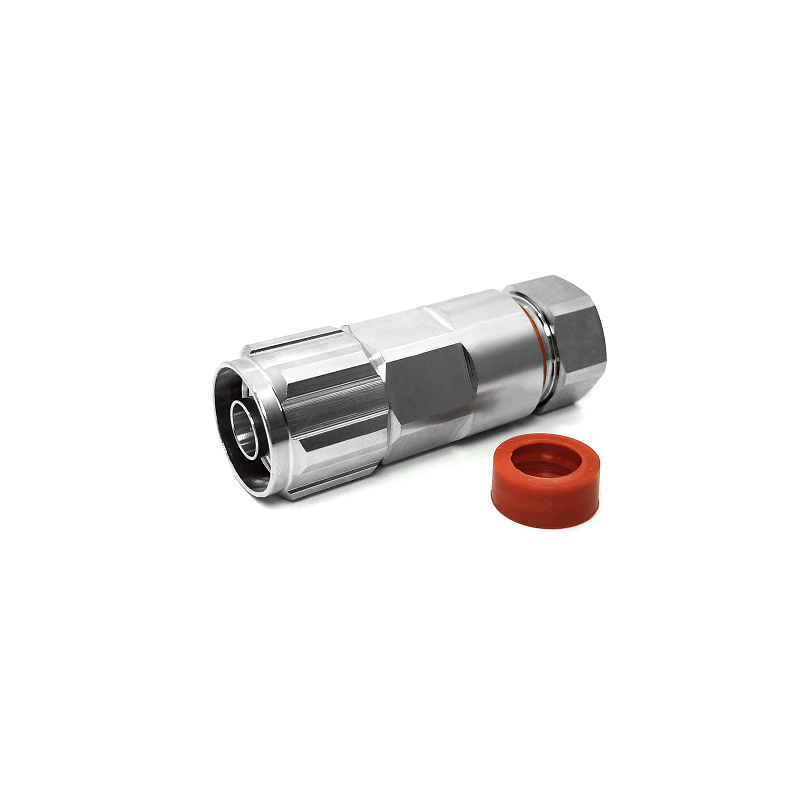
For an original equipment manufacturer (OEM) engineering team, specifying protective coatings should always be a calculated decision rather than an automatic check-box item. An n type coax connector can operate with absolute reliability without extra anti-corrosion treatment when its base alloy, plating specification, sealing assembly, and actual operating environment already manage exposure risks. The key word here is "can." Marking additional protection as optional does not imply it is unnecessary across every outdoor deployment.
When reviewing engineering drawings, RF design teams routinely ask whether an n type coax connector requires extra passivation, heavy plating, or specialized salt-spray validation. The correct engineering response starts by defining where the component will function throughout its operating lifespan, rather than applying a blanket plating callout across all bill-of-materials.
Baseline Designs Matching Controlled Indoor Environments
An n type coax connector housed within a dry, climate-controlled enclosure operates under a vastly different corrosion profile than one attached to a coastal cellular tower, an underground transit node, or marine radar gear. In protected indoor settings, the equipment cabinet eliminates direct rainfall, salt fog, ultraviolet radiation, and corrosive chemical deposition. If the chosen brass or stainless steel body material and gold or silver contact plating match that ambient environment, adding extra anti-corrosion processing increases unit costs and manufacturing lead times without delivering measurable functional value.
OEM procurement specifications benefit from separating interface geometry from environmental duty ratings. While the standard N-type interface governs high-frequency RF matching and mechanical coupling, environmental criteria should explicitly detail actual exposure conditions: controlled indoor dry, sheltered outdoor, industrial atmosphere, high humidity, or direct salt-laden air.
Scenarios Where Extra Coatings Are Unnecessary
-
Conditioned Equipment Bays: The n type coax connector remains inside server racks, laboratory test benches, or sealed indoor transceivers without condensation risk.
-
Short-Term Protected Deployments: The cable assembly serves temporary indoor testing setups or remains fully sheltered during transport and integration.
-
Galvanically Compatible Interfaces: Base metals and surface plating systems naturally match mating jacks and enclosure walls, preventing galvanic corrosion.
-
Minimal Contaminant Exposure: The environment lacks salt spray, chemical fumes, frequent washdowns, or conductive industrial dust.
-
Engineered Moisture Boundaries: Gasket designs, boots, and entry glands completely block moisture from reaching the n type coax connector interface.
In these specific scenarios, treating secondary coatings as optional is a sound engineering conclusion backed by operational facts. However, omitting extra treatment should never mean leaving surface finishes undefined. Assembly drawings must still state exact base materials, plating thickness tolerances, visual standards, and quality inspection guidelines.
Environmental Variables That Shift the Engineering Decision
Secondary protection becomes mandatory the moment liquid moisture lingers around connector threads or when environmental pollutants form a conductive electrolyte path. Outdoor telecom infrastructure, port-side radio nodes, agricultural sensors, and humid industrial plants require a conservative material review. Thermal cycling demands equal attention; rapid temperature drops create pressure differentials that pull ambient moisture into unsealed threaded joints.
When evaluating salt exposure, testing standards such as IEC 60068-2-52 provide cyclic salt-mist verification methods to establish realistic qualification benchmarks. This test procedure serves to validate environmental durability, rather than proving that every single n type coax connector requires identical exposure times or heavy surface layers. Furthermore, utilizing the IEC 60512 test series allows engineers to measure how mechanical wear and environmental stress impact contact resistance over prolonged cycles.
Mitigating Galvanic Corrosion Across the Entire Interconnect
Corrosion risks rarely remain confined to the outer connector shell. Moisture traps frequently form around exposed braid terminations, crimp ferrules, mounting nuts, or unmated interface ports. Even the highest grade anti-corrosion treatment on an n type coax connector cannot offset water creeping through a poorly sealed cable jacket or an improperly torqued coupling nut.
Engineers should specify protective dust caps, precise mounting torque limits, silicon sealing boots, and proper handling procedures whenever field conditions introduce moisture risks. Matching metals across the entire signal path prevents galvanic action from destroying contact surfaces over time.
Environmental Review for N Type to SMA Transitions
Incorporating an n type to sma adapter or jumper assembly introduces an additional mechanical interface, alongside potential variations in base metals and plating chemistries. The evaluation remains tied to operating environment: will the n type to sma connection sit safely inside a shielded benchtop instrument, or will it endure humidity changes near an outdoor antenna feed?
Because smaller SMA interfaces feature finer thread pitches and thinner outer walls, they are often more vulnerable to moisture trapping than robust N-type interfaces. Verifying mating sequences, minimizing adapter stack-ups, and capping unused ports reduce points where condensation accumulates.
Rather than ordering an n type to sma transition based on interface names alone, system designers should review gender, system impedance, operating frequency, cable flexibility, housing clearance, and atmospheric exposure as a single, unified assembly requirement.
Practical OEM Engineering Checklist
-
Document the operational environment in concrete metrics: indoor versus outdoor, condensation risk, humidity ranges, salt spray levels, and washdown chemicals.
-
Audit all mating interfaces to identify potential galvanic mismatches around the n type coax connector.
-
Confirm baseline plating specs (such as tri-metal or gold plating thickness) in supplier drawings instead of assuming generic finishes.
-
Determine whether environmental qualification under standards like IEC 60068-2-52 is necessary for the final application.
-
Inspect cable entry seals, weather boots, protective caps, and torque guidelines across the full interconnect path.
-
Evaluate both interfaces on an n type to sma assembly to ensure smaller connectors meet the same environmental standard.
-
Lock the engineering rationale into the permanent OEM specification so purchasing, manufacturing, and quality teams share a single baseline.
Precision Manufacturing and Plating Control
Balancing cost, RF performance, and environmental durability requires an experienced interconnect manufacturing partner. WORLDPEAK provides reliable RF connector manufacturing, specialized surface plating options, and custom cable assembly solutions for global technology integrators.
By offering expert material selection, precision tri-metal plating, and rigorous environmental testing matching IEC and MIL standards, WORLDPEAK ensures every n type coax connector and adapter assembly meets exact project demands—delivering uncompromised signal integrity across both controlled indoor systems and rugged outdoor environments.





