 EN

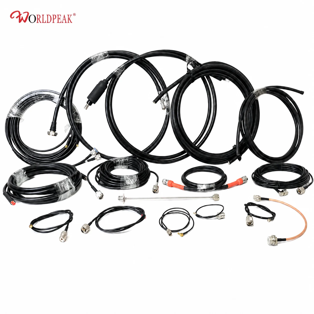
In modern telecommunications infrastructure, cellular base stations, broadcast transmitters, and satellite earth stations demand robust transmission lines capable of carrying massive RF power with minimal signal degradation. When standard 1/2-inch flexible jumpers reach their thermal and attenuation limits, network deployment engineers rely on a 7/8-inch coaxial cable as the primary feeder for high-power RF systems.
At Worldpeak, engineering high-performance coaxial interconnects requires a deep understanding of RF power handling, dielectric stability, and mechanical durability under extreme environmental conditions. This technical analysis explores why a 7/8-inch coaxial cable serves as the optimal feeder for high-power RF applications, examining its attenuation profile, structural integrity, and installation best practices.
Mechanical Architecture and Electrical Impedance
A high-performance 7/8-inch coaxial cable is designed to maintain a strict 50-ohm characteristic impedance across broad frequency bands (typically up to 5 GHz). Because high-power RF transmissions generate substantial electrical currents on the conductor surfaces and high voltage gradients across the dielectric layer, physical dimensions must be held to tight manufacturing tolerances.
Key structural components engineered by Worldpeak include:
-
Inner Conductor: Constructed from copper-clad aluminum (CCA) or smooth corrugated copper tubing, balancing electrical conductivity with mechanical weight reduction.
-
Foam Dielectric: High-foaming polyethylene (PE) dielectric with a high gas-injection ratio ensures low permittivity, maintaining uniform impedance and reducing signal dielectric losses.
-
Outer Conductor: Helically or annularly corrugated copper shield providing 100% RF shielding efficiency, structural flexibility, and high resistance to crushing forces during tower installation.
-
Outer Jacket: UV-inhibited, flame-retardant polyethylene or low-smoke zero-halogen (LSZH) jacket engineered for multi-decade exposure to outdoor weather.
Using a 7/8-inch coaxial cable as a feeder for high-power RF provides significantly larger surface area on both inner and outer conductors compared to smaller cable sizes, directly translating to lower skin-effect resistance and lower heat generation.
RF Attenuation and Power Handling Capability
The selection of a 7/8-inch coaxial cable as a feeder for high-power RF is primarily driven by attenuation limits and average power handling requirements. Signal loss increases with operating frequency and cable length. For tall broadcast towers or macro cell sites where feeder runs exceed 30 to 50 meters, higher attenuation directly converts precious transmitter power into wasted heat.
Power Dissipation and Attenuation Profile
The table below outlines typical attenuation and peak/average power limits for a 7/8-inch coaxial cable manufactured by Worldpeak under ambient operating conditions (20 degrees C at sea level):
| Operating Frequency (MHz) | Attenuation (dB / 100 meters) | Max Average Power Rating (kW) | Application Context |
| 100 MHz | ~1.15 | ~11.5 | FM Radio Broadcasting & VHF |
| 450 MHz | ~2.55 | ~5.2 | PMR & Trunked Land Mobile Radio |
| 900 MHz | ~3.75 | ~3.5 | GSM 900 & Cellular Macro Base Station Feeder |
| 1800 MHz | ~5.50 | ~2.4 | DCS / UMTS High-Capacity Sites |
| 2100 MHz | ~6.05 | ~2.1 | 3G / 4G LTE Mid-Band Feeder Lines |
| 2700 MHz | ~7.00 | ~1.7 | Sub-6 GHz 5G NR Infrastructure |
When deploying a feeder for high-power RF, maintaining a low VSWR (Voltage Standing Wave Ratio) is vital. High reflections create localized voltage peaks along the 7/8-inch coaxial cable, which can trigger dielectric breakdown or cause transmitter shutdown.
Passive Intermodulation (PIM) and Return Loss Verification
In modern multi-carrier cellular networks, Passive Intermodulation (PIM) is a critical performance parameter. PIM occurs when high-power RF signals pass through non-linear junctions in the transmission path, generating unwanted interference that degrades receiver sensitivity.
To ensure pristine signal integrity, a 7/8-inch coaxial cable operating as a feeder for high-power RF must achieve low PIM performance (typically better than -160 dBc @ 2x20W / +43 dBm tones).
Worldpeak enforces strict manufacturing and quality controls to minimize PIM drivers:
-
Seamless Outer Shield: Precision corrugation eliminates micro-gaps in the outer conductor.
-
Corrosion-Resistant Plating: Utilizing high-grade silver or tri-metal (white bronze) plating on compatible DIN 7/16 or 4.3-10 connectors.
-
Torque Control: Ensuring mechanical connections are tightened to specification using calibrated torque wrenches during installation.
International Standards, Quality Assurance, and EEAT Compliance
Industrial reliability in telecommunications infrastructure depends on strict compliance with global engineering standards. Worldpeak manufactures and tests each 7/8-inch coaxial cable used as a feeder for high-power RF in accordance with recognized international protocols:
-
IEC 61196 Series: International electrical and mechanical performance standards for coaxial communication cables.
-
IEC 60332 / IEC 60754: Flame propagation, halogen acid gas content, and smoke density testing for indoor/tunnel feeder deployments.
-
ISO 9001 & ISO 14001: Quality management and environmental protection certification governing production facilities.
-
Factory Quality Acceptance Testing (FAT): Every production batch undergoes 100% sweep testing on vector network analyzers (VNA) to confirm VSWR <= 1.13 across the operating frequency band, followed by high-voltage dielectric withstand testing and water-tightness pressure verification.
Installation Best Practices and System Integration
Proper installation procedures are critical to maintaining the rated performance of a 7/8-inch coaxial cable. Key site guidelines include:
-
Minimum Bending Radius: Adhere strictly to the manufacturer's specified single bend (typically ~120 mm) and repeated bend radius (typically ~250 mm) to prevent outer conductor buckling or dielectric deformation.
-
Feeder Clamping: Secure the cable along tower legs using UV-resistant stainless steel angle clamps spaced at recommended intervals (1.0 to 1.5 meters) to prevent wind loading damage.
-
Weatherproofing and Grounding: Install grounding kits at the top of the tower, bottom of the tower, and entry port to divert lightning surges. Apply heat-shrink or multi-layer weatherproofing tape over all connector junctions to prevent moisture ingress.
By integrating robust mechanical design with precise RF performance, a 7/8-inch coaxial cable engineered by Worldpeak serves as a dependable, low-loss feeder for high-power RF communication networks globally.
To review complete specifications and complementary RF interconnect components, explore our





