 EN

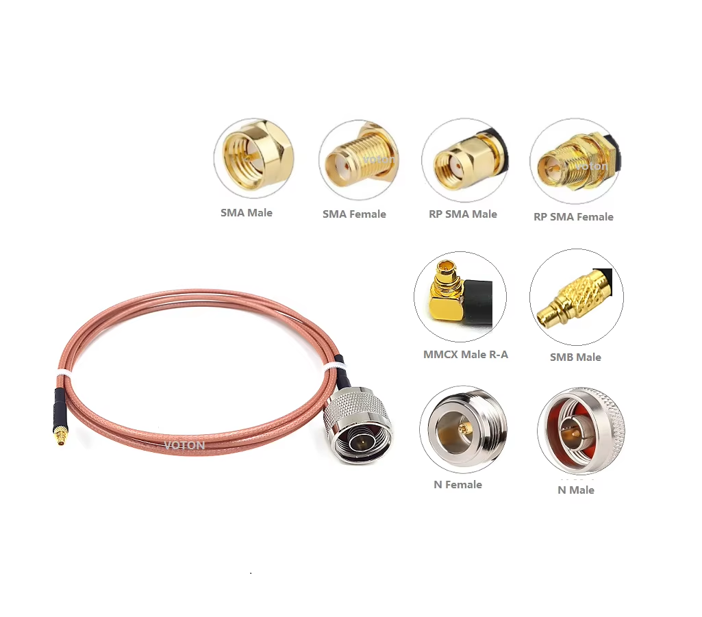
In modern RF systems engineering, a bulkhead SMA connector is far more than a simple mechanical fastener or cabinet pass-through. It forms an integral part of the transmission line, bridging external field cabling with sensitive internal electronics, printed circuit boards (PCBs), or internal flexible jumpers. Whether deployed in outdoor cellular base stations, industrial IoT enclosures, military-grade communication racks, or high-precision test fixtures, a correctly specified and installed SMA bulkhead preserves characteristic 50-ohm impedance and protects signal integrity.
When evaluating panel-mount coaxial interfaces, engineers must balance electrical performance (VSWR, insertion loss, shielding) with mechanical reliability (torque limits, anti-rotation keying, panel thickness) and environmental sealing (such as an IP67 SMA connector assembly).
Understanding the Bulkhead SMA Connector Envelope
A bulkhead SMA connector features an elongated, externally threaded body designed to pass through a pre-drilled or punched panel hole. The assembly is secured against the enclosure wall using a combination of lock washers, hex mounting nuts, and optional silicone O-rings or conductive gaskets.
While many procurement requests loosely reference an SMA bulkhead, precise gender configurations must be frozen prior to manufacturing:
-
Standard Polarity vs. Reverse Polarity (RP-SMA): Standard SMA female bulkhead components feature a hollow center receptacle designed to mate with a male pin. Reverse-polarity variants swap center contact geometries to meet regulatory requirements (e.g., FCC rules for Wi-Fi equipment).
-
Rear Termination Style: The internal side of an SMA female bulkhead may feature a solder cup, micro-strip launch tab, printed circuit board crimp legs, or a direct coaxial cable crimp socket (such as for RG174, RG316, or LMR100 lines).
-
Mounting Flange Geometry: Depending on vibration levels and panel thickness, pass-through designs utilize single-D cutouts, double-D anti-rotation flats, or 4-hole square flange bulkhead housings.
Key Selection Criteria: Electrical, Mechanical, and Environmental Parameters
To prevent unexpected link degradation or field failures, compare your system limits against the component parameters outlined below:
|
Technical Parameter
|
Standard Commercial Spec
|
Industrial Ruggedized Spec
|
High-Frequency Weatherproof Spec
|
|---|---|---|---|
|
Interface Series
|
Standard SMA bulkhead
|
Heavy-duty SMA female bulkhead
|
Sealed IP67 SMA connector
|
|
Operating Frequency
|
DC to 6.0 GHz
|
DC to 12.4 GHz
|
DC to 18.0 GHz
|
|
Impedance / VSWR
|
50 Ohm / < 1.30:1
|
50 Ohm / < 1.20:1
|
50 Ohm / < 1.15:1
|
|
Body Plating
|
Gold flash or nickel-plated brass
|
Passivated stainless steel
|
Gold-plated brass / stainless steel
|
|
Ingress Rating
|
Unsealed (IP50)
|
Dust-resistant (IP54 / IP65)
|
Fully submersible (IP67 SMA connector)
|
|
Mating Cycles
|
100 cycles min.
|
500 cycles min.
|
1,000 cycles min.
|
When selecting an IP67 SMA connector, verify that environmental sealing applies to both the panel-to-connector interface (via internal O-rings) and the mated connector pair. Using an IP67 SMA connector ensures protection against dust ingress and water immersion up to 1 meter depth.
Step-by-Step Panel Mount Installation Workflow
Following a standardized installation protocol prevents thread stripping, gasket over-compression, and internal solder joint fatigue:
1. Inspect Panel Cutout
Verify hole diameter and anti-rotation flats. Clean and deburr the panel hole on both sides of the chassis. Ensure the cutout matches the specific bulkhead SMA connector drawing—incorporating single-D or double-D keying flats to prevent the body from spinning during cable mating.
2. Fit Sealing & Retention Hardware
Position O-ring and lock washer correctly. For weatherproof enclosures, slide the silicone sealing ring onto the outer shoulder of the IP67 SMA connector prior to inserting it through the front panel. On the interior chassis side, place the internal tooth lock washer followed by the hex retaining nut.
3. Tighten Panel Hardware
Apply calibrated torque to retaining nut. Hold the flats of the SMA female bulkhead body with a thin wrench to prevent rotation. Using a calibrated torque wrench, tighten the hex nut to the manufacturer's specified panel torque limit (typically 8 to 12 in-lbs for brass housings).
4. Connect Internal Coax or PCB
Relieve strain on internal termination. Route internal jumpers or solder launch tabs without putting direct axial strain on the SMA bulkhead tail. Maintain recommended bend radii for coaxial cables to prevent dielectric deformation and reflection spikes.
5. RF Acceptance Sweep Testing
Perform VNA sweeps and continuity checks. Measure DC continuity and insulation resistance, followed by a Vector Network Analyzer (VNA) sweep across your operational frequency band to verify return loss (VSWR) meets design limits.
Preventing Common Field Failure Modes
-
Gasket Over-Compression: Excess mounting torque on an IP67 SMA connector can pinch or pinch out the silicone O-ring, creating micro-gaps that allow moisture ingress over thermal cycles.
-
Unwanted Rotational Stress: Torque applied to external cable couplings can cause an un-keyed SMA female bulkhead to spin, twisting and snapping internal solder leads or PCB surface-mount pads.
-
Impedance Discontinuities: Metal burrs, paint overspray on grounding faces, or excessive solder on the center pin disrupt the 50-ohm geometry of the bulkhead SMA connector, causing reflected energy and higher insertion loss.
Engineers and sourcing teams can reference complete product specifications and custom pre-terminated cable assemblies through WORLDPEAK , a specialized manufacturer of high-reliability SMA bulkhead components and RF interconnect solutions.
Pre-Release Quality Acceptance Checklist
-
Is the exact panel cutout drawing (including D-flat dimensions) verified against the bulkhead SMA connector datasheet?
-
Have system frequency (DC–18 GHz) and impedance (50 Ohm) requirements been validated for the complete assembly?
-
Are sealing O-rings and IP ratings verified for all IP67 SMA connector panel locations exposed to weather or washdown?
-
Is mounting hardware tightened using calibrated torque wrenches to prevent thread or gasket damage?
-
Have VNA return loss and insertion loss sweep tests been documented for site acceptance records?





