 EN

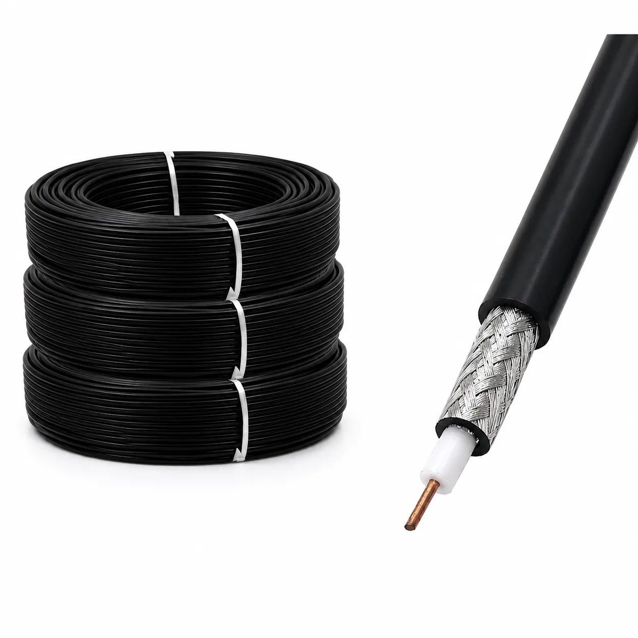
Connectorized Coaxial Jumper: Pre-Made RF Solutions
A connectorized coaxial jumper is more than a short link between two ports. In an antenna line, base-station rack, or RF laboratory, it is the assembly that carries a controlled impedance from one defined interface to the next. Choosing a pre-made assembly with the right cable, connectors, length, and environmental treatment helps keep insertion loss, return loss, and mechanical strain under control.
For engineers and buyers, the useful starting point is the signal path rather than the connector alone. Define frequency, power, impedance, route length, bend constraints, indoor or outdoor exposure, and the mating interfaces. That approach makes a connectorized coaxial jumper easier to specify and easier to inspect on arrival.
Where a connectorized coaxial jumper fits
At an antenna, a jumper can bridge a feeder, a lightning-protection device, and the radio interface. In a base-station cabinet, it can make a serviceable connection between passive equipment and a distribution panel. In a laboratory, it can connect instruments, fixtures, and devices under test without asking technicians to terminate cable on the bench. The value of a pre-made assembly is repeatability: the cable type, connector pairing, and finished length are defined before installation.
That same logic matters when a coaxial phase shifter or a calibrated test path is involved. Electrical length and connector consistency can affect phase-sensitive work, so a generic patch lead is not automatically interchangeable with a documented assembly. Where phase matching, insertion-loss records, or VSWR sweeps are needed, request those requirements during specification review.
Why the cable specification changes signal loss
Every connectorized coaxial jumper introduces attenuation that rises with frequency and route length, while mismatch at either end can add reflections. A thin, flexible cable may be the right answer for a tight instrument panel, but it may not be the appropriate choice for a long outdoor route. Conversely, a larger low-loss cable can reduce attenuation but needs more room for routing and a larger bend radius.
| Cable family | Typical strength | Good fit | Watch item |
|---|---|---|---|
| RG58 | Flexible, compact handling | Short, lower-demand bench and service links | Loss becomes more significant as frequency and length rise |
| RG8X | Middle ground between size and handling | Moderate-length mobile or equipment connections | Confirm the actual frequency and power requirement |
| LMR400-type | Lower-loss construction for longer runs | Outdoor feeder sections and loss-sensitive RF paths | Requires more routing space and careful bend control |
These are application comparisons, not a substitute for a cable data sheet. A procurement specification should name the frequency range, maximum acceptable insertion loss, impedance, connector gender, cable length, and any test requirement. For a low-loss option to evaluate against the system budget, see the LMR400 Low-Loss 50 Ohm Coaxial Cable. For a smaller 50-ohm cable reference, the Worldpeak RG196 50-Ohm Coaxial Cable guide is also available.
Do not substitute cable families by name alone
An rg6 cable is commonly associated with 75-ohm video and broadband distribution work. It should not be treated as a drop-in substitute for a 50-ohm RF system simply because the connectors appear adaptable. Impedance, frequency behavior, connector family, and intended equipment all need to match. The same caution applies when a connectorized coaxial jumper crosses between telecom hardware and laboratory instruments: verify the port standard before ordering.
For outdoor antenna systems, consider the complete protection chain. Surge arresters should be selected for compatible interfaces and installed according to the site grounding plan. The jumper on either side must be short enough for practical routing, but long enough to avoid tension at the connector. A well-specified connectorized coaxial jumper supports the installation; it does not replace correct grounding or a coordinated surge-protection design.
OEM options and realistic ordering questions
OEM and private-label programs are most useful when the standard catalog length or connector pair does not fit the equipment layout. A supplier can review a requested cable family, length, mixed connector configuration, jacket need, labeling, packaging, and documentation. For deployments that need incoming inspection, ask whether each connectorized coaxial jumper can be supplied with insertion-loss and VSWR sweep data.
Lead time should be confirmed against the actual configuration, order quantity, connector availability, and any testing or labeling requirements. Avoid treating a quoted sample lead time as a promise for a production rollout. A clear request-for-quotation should include drawings or connector callouts, quantity by length, environmental conditions, and the acceptance criteria. This reduces rework later and gives the manufacturer a sound basis for scheduling.
Installation checklist: bending, support, and weatherproofing
- Inspect before mating. Verify connector type, gender, cable label, and protective caps. Keep mating surfaces clean and avoid cross-threading.
- Respect the specified bend radius. Do not kink the cable or force a turn immediately behind a connector. Bend-radius guidance is cable-specific; follow the manufacturer’s published value.
- Provide strain relief. Support longer or heavier assemblies so the connector is not carrying the cable weight or wind load.
- Build water management into outdoor routes. Position cables so water does not track into a connector, and use a drip loop where the route permits.
- Weatherproof the mated interface. Use the site-approved sealing method, often overlapping self-fusing tape with an appropriate outer protection layer. Inspect the seal after service work.
- Record the installed assembly. Capture part number, length, route, connector pair, and test documentation so future maintenance does not rely on guesswork.
Specify the assembly around the RF path
A suitable connectorized coaxial jumper meets the electrical budget and survives the physical installation without unnecessary complexity. Start with the system impedance and frequency, then select cable construction for loss and flexibility, define the connector interfaces, and add test, labeling, and weatherproofing requirements where the application calls for them. This method produces a pre-made RF solution that is easier to order, install, and maintain.





