 EN

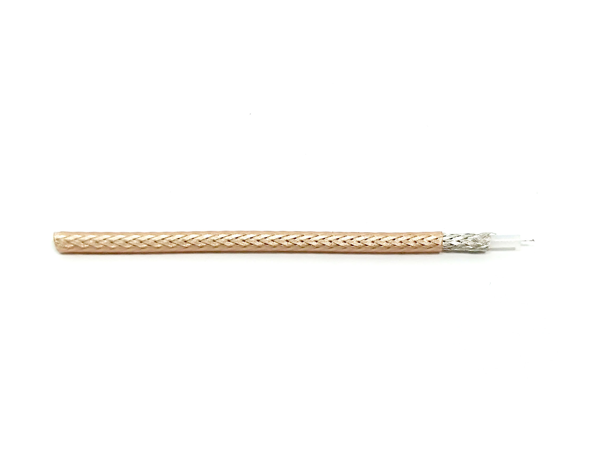
In original equipment manufacturing (OEM) programs, short-run and pilot production phases represent critical inflection points for system validation. High-frequency custom rf cables rarely fail in the field because a buyer forgot to place an order. Instead, production delays and performance issues occur when a purchase specification vaguely states "50-ohm assembly, 1 m" without defining connector keying, pin clocking orientation, bend radius thresholds, VNA sweep frequencies, or inspection evidence. Sourcing engineering teams must treat custom rf cables as fully controlled, precision-engineered components rather than off-the-shelf cut wire.
Whether your pilot build requires high-frequency coaxial feeds, hybrid power-RF jumpers, custom medical cables with biocompatible jacketing, tactile custom push pull cables for quick-latch equipment, or compact custom jst cables for internal power and signal distribution, establishing a rigorous pre-production technical package prevents batch-wide rework and controls procurement lead times.
Step 1: Interface Definition & Complete Electrical Path Specification
A robust engineering specification for custom rf cables starts at both connection endpoints, working inward toward cable geometry. Specifying only the cable family without freezing the exact connector interface leaves key variables open to interpretation.
When preparing documentation for custom rf cables, define the exact connector series (e.g., SMA, N-Type, 4.3-10, BNC), gender, polarity (standard or reverse polarity), coupling method (threaded, push-pull, or bayonet), and panel mounting footprint. Following interface selection, establish the complete electrical path parameters across the operational environment:
-
Impedance & Bandwidth: Define nominal characteristic impedance (typically 50 Ohm or 75 Ohm) and the maximum upper frequency limit (e.g., DC to 6 GHz or DC to 18 GHz).
-
Attenuated Link Budget: Set strict maximum insertion loss limits (in dB/meter) and Voltage Standing Wave Ratio (VSWR) thresholds (e.g., VSWR < 1.15:1) across the full operational sweep band for all custom rf cables.
-
Phase Control & Electrical Length: Specify whether the signal path requires absolute phase matching (e.g., within +/- 2 degrees at 5.8 GHz) or tightly controlled electrical delay times across cable sets.
-
Mechanical Envelope: State exact finished assembly lengths along with allowable physical tolerances (+/- 5 mm vs. +/- 20 mm) and minimum dynamic/static bend radiuses.
Step 2: The OEM Technical Package & Hybrid Cable Requirements
Before issuing a Request for Quotation (RFQ) for custom rf cables, compile a complete engineering control package to eliminate back-and-forth technical queries:
-
Assembly Master Drawing: Include a uniquely numbered, revision-controlled drawing detailing End A and End B connector series, pinout configurations, clocking orientation angles, and heat-shrink sleeve placement.
-
Raw Material Specifications: State approved raw coaxial cable models, jacket material types (such as FEP, PTFE, low-smoke zero-halogen LSZH, or polyurethane), and plating callouts for contacts and housings.
-
Hybrid & Mixed Assembly Rules: Specify keying, latch retention force, and contact plating for integrated custom push pull cables. For board-level power or control lines utilizing custom jst cables (such as JST PH, XH, or SH series), define wire gauge, pin-to-wire mapping, housing orientation, and strain-relief geometry. When designing custom medical cables, mandate biocompatible outer materials (ISO 10993 compliance), sterilization resistance (autoclave or EtO gas), and non-magnetic conductor construction where required.
Step 3: Evaluating Short-Run Suppliers Beyond Unit Price
Evaluating supplier capability for custom rf cables requires looking beyond base piece-part pricing. Short-run OEM success relies on process repeatability, tooling precision, and comprehensive quality documentation.
| Evaluation Metric | General Commercial Cable Supplier | Precision OEM Cable Manufacturer |
| RF Verification Scope | Basic DC continuity & short testing | 100% VNA sweep (VSWR, Insertion Loss, PIM) for custom rf cables |
| Specialized Cable Expertise | Standard PVC/PE coaxial assemblies | Certified builds for custom medical cables & specialized jackets |
| Hybrid Wire Assembly | Limited to standard coaxial crimping | Full support for custom push pull cables and micro-pitch custom jst cables |
| Document Deliverables | Standard commercial invoice | First-Article Inspection (FAI) reports, C of C, lot traceability logs |
| Change Control Rules | Unannounced material substitutions | Locked BOM with formal ECO sign-off before mass production |
When sourcing complex hybrid wire harnesses or precision coaxial jumpers, engineering teams rely on verified manufacturing partners like
Step 4: Quality Acceptance Protocols & First-Article Sign-Off
To establish a bulletproof quality framework for custom rf cables, implement a structured first-article inspection (FAI) and lot release workflow:
Review the engineering drawing for custom rf cables, confirming that connector interfaces, length tolerances, clocking angles, and hybrid wire pinouts for custom jst cables match the design intent.
The factory builds first-article samples. Inspectors verify physical dimensions, contact plating, crimp height, boot shrink quality, and latch engagement on custom push pull cables.
Perform VNA sweep testing across the specified frequency band to measure VSWR and insertion loss. For custom medical cables, confirm jacket insulation resistance, dielectric withstand voltage, and material cleanliness compliance.
Formal approval locks the sample baseline, drawing revision, and bill of materials. The factory executes production with lot traceability labels attached to every shipment carton.
Step 5: OEM Pre-Release Verification Checklist
Before releasing purchase orders for custom rf cables, run through this final technical release checklist:
-
Is the master drawing revision uniquely numbered and agreed upon by both buyer and supplier engineering teams?
-
Are frequency bands, maximum VSWR limits, and insertion loss limits explicitly stated for all custom rf cables?
-
Have keying orientations and strain relief boots been verified on all custom push pull cables?
-
Are pin-to-wire schedules, housing lock directions, and wire gauges fully documented for all custom jst cables?
-
Do documentation requirements for custom medical cables include biocompatibility certs, sterilization ratings, and complete material traceability records?
-
Has a statistical lot acceptance plan (100% electrical sweep vs. sampling) been locked for serial production runs?
By enforcing controlled drawings, defining clear electrical acceptance test limits, and partnering with a qualified manufacturer, sourcing teams eliminate supplier risk, accelerate pilot build approvals, and secure reliable high-performance cable assemblies.





