 EN

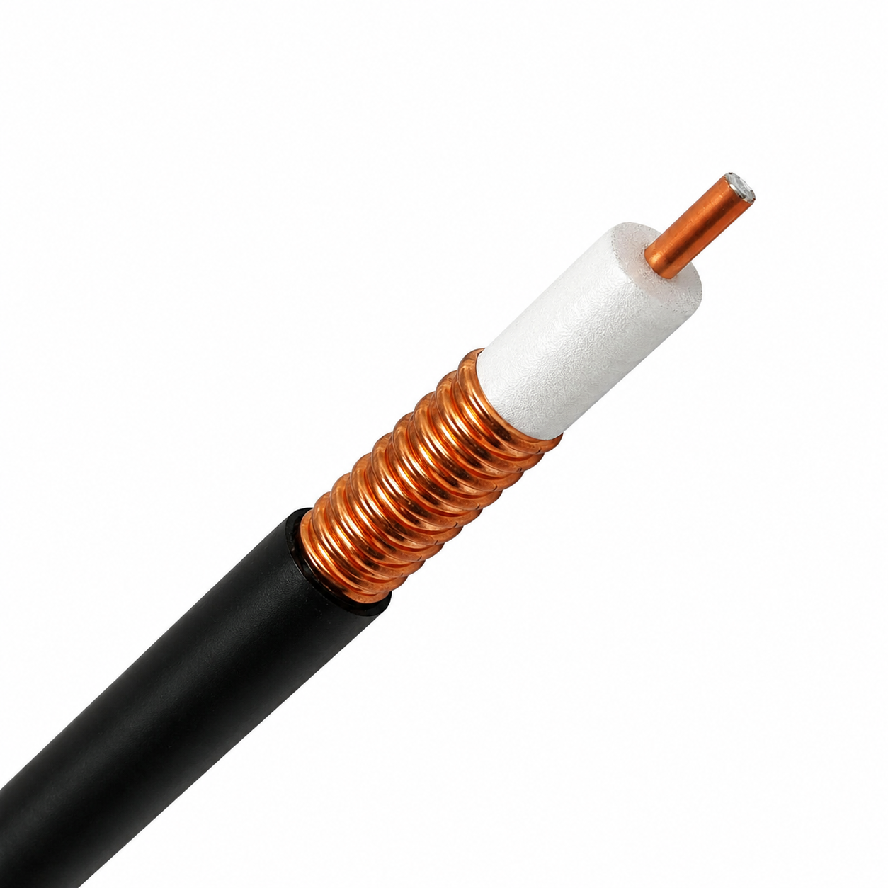
In modern wireless communication networks, the transmission line bridging the base station transceiver and the radiating antenna array is a critical determinant of overall system efficiency. A high-gain antenna system yields limited performance enhancements if the transmission path introduces excessive attenuation, phase distortion, or signal reflection. Deploying a high-performance feeder cable for antenna infrastructure is an essential engineering task that dictates link budget viability, signal-to-noise ratio, and multi-year operational reliability.
At Worldpeak, engineering advanced RF interconnect solutions requires combining state-of-the-art material science with precise field execution protocols. This comprehensive technical guide explores the fundamental engineering principles governing antenna feedline selection and establishes actionable procedures for flawless coaxial cable installation across telecommunications towers, industrial sites, and distributed antenna systems.
Core Engineering Parameters in Antenna Feedline Selection
Successful antenna feedline selection extends far beyond simply matching impedance ratings or connector interfaces. Radio frequency (RF) engineers must simultaneously evaluate multiple electrical, mechanical, and environmental constraints to prevent premature transmission line degradation and power loss.
When evaluating a prospective feeder cable for antenna deployment, network designers must analyze several critical variables:
-
Operating Frequency Bands: Attenuation losses scale exponentially with frequency. A transmission line that delivers acceptable performance at VHF bands may exhibit prohibitive attenuation when deployed in sub-6 GHz or millimeter-wave 5G infrastructure.
-
Shielding Effectiveness and EMI Resistance: In densely populated urban corridors or high-interference industrial environments, outer conductor shielding must guarantee total containment of RF energy while blocking external electromagnetic interference (EMI).
-
Power Handling and Thermal Dissipation: High-power broadcast transmitters and macro cell sites generate substantial internal heating. The cable must safely dissipate thermal energy without compromising the structural integrity of the internal dielectric layer.
By aligning these geometric and electrical properties with the target operational frequency, engineers establish a solid foundation during antenna feedline selection that safeguards long-term system integrity.
Technical Parameter Comparison Matrix
To assist system integrators and network planners during antenna feedline selection, the following parameter matrix contrasts key performance metrics across standard coaxial cable categories engineered and manufactured by Worldpeak:
| Cable Series & Size | Outer Diameter | Attenuation @ 900 MHz (dB/100m) | Max Operating Frequency | Primary Field Deployment Context |
| 1/4-Inch Superflexible | 7.6 mm | ~11.5 dB | 6.0 GHz | Equipment jumpers, tight indoor cabinet routing |
| 3/8-Inch Flexible | 10.2 mm | ~6.8 dB | 5.5 GHz | Rooftop small-cell links, compact enclosures |
| 1/2-Inch Corrugated | 13.2 mm | ~3.8 dB | 4.8 GHz | Macro cell site jumpers, medium-run towers |
| 7/8-Inch Corrugated | 24.8 mm | ~2.1 dB | 3.0 GHz | Cellular base station main towers, broadcast feeds |
| 1-1/4-Inch Coaxial | 35.5 mm | ~1.4 dB | 2.5 GHz | Long-run high-power backbones, radar links |
Best Practices for Precision Coaxial Cable Installation
Even the most technologically advanced feeder cable for antenna networks will experience catastrophic performance failure if subjected to mechanical abuse or improper handling during deployment. A disciplined, methodical approach to coaxial cable installation protects the delicate internal foam dielectric and preserves the stable 50-ohm characteristic impedance required for low VSWR.
Field engineers and installation technicians must enforce the following procedural safeguards:
-
Strict Adherence to Bending Radii: Pulling cables around sharp structural corners or forcing tight bends can deform the outer corrugated copper shield. Installers must strictly respect manufacturer-specified minimum single-bend and repeated-bend radius limits (typically maintaining 10x to 15x the outer diameter).
-
Vertical and Horizontal Clamping Schedules: During coaxial cable installation on tall lattice or monopole towers, use high-grade stainless steel angle clamps and snap-in hangers spaced evenly at 1.0 to 1.2-meter intervals. This prevents wind-induced vibration fatigue and gravitational cable sagging.
-
Environmental Weatherproofing of Junctions: Connector interfaces exposed to severe outdoor elements must be protected using multi-layer weatherproofing systems, including cold-shrink tubing, butyl rubber mastic sealing tape, and UV-resistant electrical tape to completely block moisture ingress and oxidation.
Manufacturing Standards, Quality Assurance, and EEAT Compliance
Industrial-grade telecommunications infrastructure demands rigorous manufacturing standards to ensure flawless field performance. Worldpeak manufactures every feeder cable for antenna architecture in strict compliance with globally recognized quality management and safety protocols:
-
International Standards Alignment: All coaxial transmission lines are engineered to comply with IEC 61196 specifications for coaxial communication cables, alongside IEC 60332 flame-retardant performance ratings.
-
100% Factory Acceptance Testing (FAT): Every production reel undergoes rigorous sweep testing utilizing advanced Vector Network Analyzers (VNA) to verify that return loss (VSWR) remains below strict threshold limits across the designated frequency spectrum.
-
Environmental Stress Screening: Quality verification protocols incorporate thermal aging tests, tensile strength evaluations, and high-pressure water immersion checks to validate multi-decade outdoor durability.
Conclusion and Integration
Achieving a resilient, high-performance wireless transmission link relies on the precise synergy between meticulous antenna feedline selection, disciplined coaxial cable installation, and uncompromised manufacturing quality. A properly deployed feeder cable for antenna architecture guarantees minimal signal attenuation, superior Passive Intermodulation (PIM) performance, and decades of dependable field operation.
For comprehensive technical data sheets, custom cable assemblies, and specialized RF interconnect solutions for your upcoming infrastructure project, explore our





