 EN

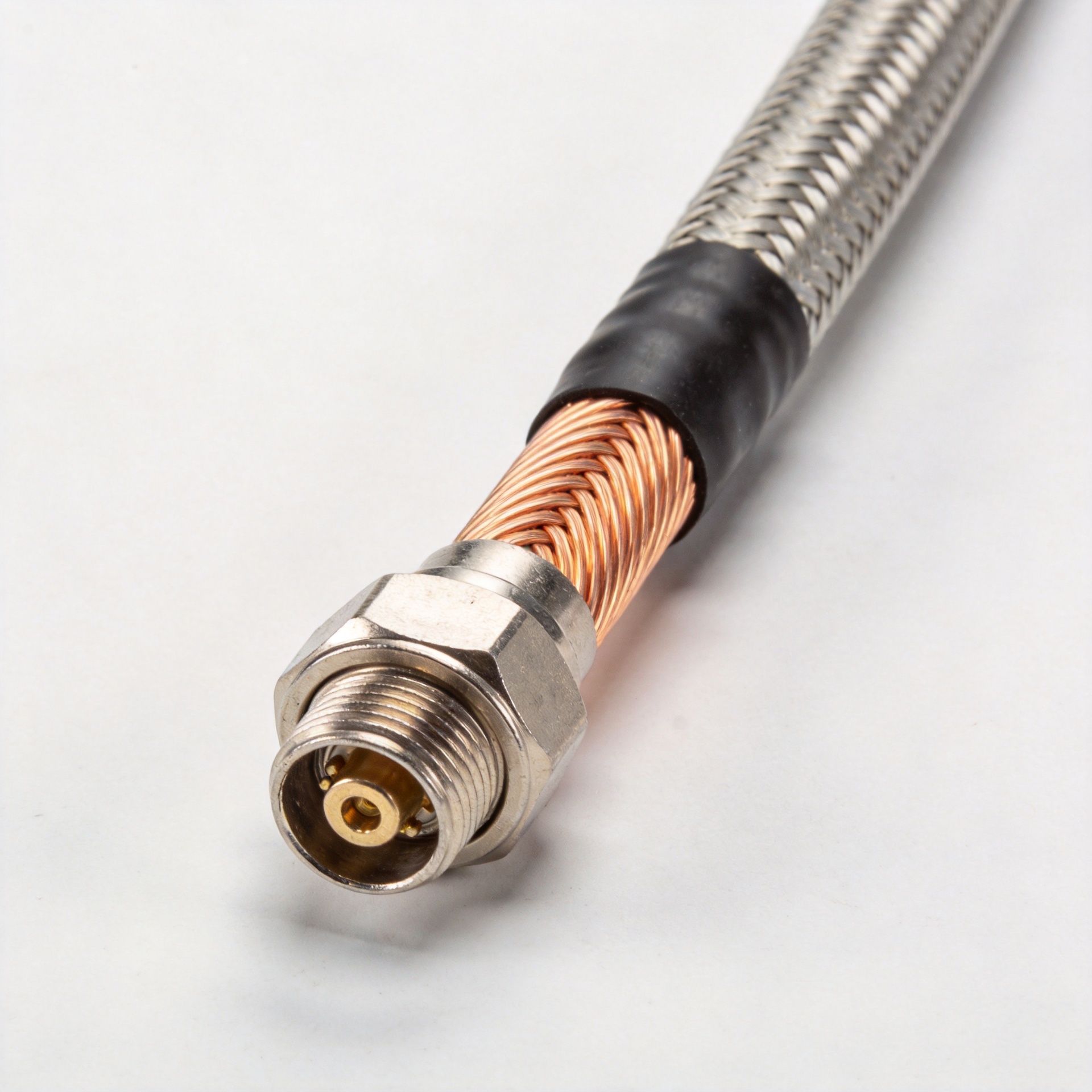
Deploying modern wireless communication infrastructure, satellite ground stations, point-to-point microwave links, and cellular backhaul networks requires uncompromising signal integrity. At microwave and millimeter-wave frequencies, signal degradation becomes a primary bottleneck that directly threatens system availability and link budgets. Selecting and deploying a specialized high-frequency feeder cable is vital for maintaining low insertion loss, phase stability, and superior shielding effectiveness across complex GHz-range antenna runs. Inefficient cabling or poor dielectric shielding can introduce massive RF attenuation, severely degrading transmission range, signal-to-noise ratio, and receiver sensitivity. As an industry-leading manufacturer at
Attenuation Dynamics and Dielectric Selection in GHz Feeder Lines
As operating frequencies push past 3 GHz into higher microwave and millimeter-wave bands, skin effect losses and dielectric dissipation escalate rapidly. Understanding the internal physics of a high-frequency feeder cable helps engineers prevent severe signal dropout during long-distance transmission runs. Electromagnetic energy in a high-frequency system does not travel uniformly through the conductor cross-section. Instead, electromagnetic fields propagate primarily within the dielectric space between the inner and outer conductors, while currents concentrate along the narrow outer skin of the conductors.
-
Conductor Surface Topography and Skin Depth: At higher frequencies, electrical current flows strictly along the microscopic outer perimeter of the center conductor due to the skin effect. To combat excessive copper resistance at elevated frequencies, high-performance cables utilize silver-plated copper-clad aluminum or solid silver-plated copper conductors. The smooth silver plating minimizes surface roughness, reducing micro-resistance and keeping attenuation to an absolute minimum across long GHz-range antenna runs.
-
Foam vs. Solid Dielectrics: To achieve lower attenuation in long-distance GHz-range antenna runs, cellular-expanded polyethylene (PE) or low-density micro-porous PTFE dielectrics are utilized. Lower dielectric constants significantly reduce capacitance per foot, minimizing velocity factor losses and improving power handling capacity.
-
Shielding Effectiveness and EMI Suppression: Double-shielded configurations combining a bonded aluminum-tinned copper foil tape with an outer high-density tinned copper braid prevent external electromagnetic interference (EMI) ingress and signal leakage. Achieving greater than 90 dB shielding effectiveness is mandatory to protect sensitive wireless receiving equipment operating in noisy RF environments.
Technical Performance Metrics Across Microwave Frequencies
When evaluating a high-frequency feeder cable for long outdoor runs, RF design engineers must carefully balance physical cable dimensions against electrical performance parameters. Larger physical diameters generally offer lower attenuation due to decreased conductor resistance, but they trade off flexibility, minimum bend radius, and ease of installation in constrained conduits or tower rungs.
The operational success of an RF transmission line hinges on several core specifications:
-
Voltage Standing Wave Ratio (VSWR): Measures structural return loss and impedance uniformity. Poorly manufactured cables introduce impedance spikes, causing reflected power to travel back toward the transmitter.
-
Velocity of Propagation (VP): Expressed as a percentage of the speed of light in a vacuum. Advanced gas-injected foam dielectrics achieve VP ratings as high as 88% to 92%, substantially reducing phase delay.
-
Cut-off Frequency: The maximum usable frequency before higher-order waveguide modes begin to propagate inside the coaxial structure, causing dispersion and destructive distortion.
Parameter Comparison Matrix for GHz Feeder Solutions
Different deployment scenarios—such as short rooftop jumper lines versus long tower risers or heavy-duty radar feeds—require distinct cable geometries and material compositions. The table below compares common engineering parameters for high-frequency feeder cable variants used in modern GHz-range antenna runs.
| Cable Series Designation | Outer Diameter (mm / in) | Attenuation at 3 GHz (dB / 100ft) | Attenuation at 6 GHz (dB / 100ft) | Outer Shielding Type & Coverage | Primary Deployment Application |
| Low-Loss 240-Type | 6.1 mm (0.240 in) | ~13.5 dB | ~19.8 dB | Dual Shield (Bonded Foil + 90% Braid) | Equipment cabinet wiring, short patch jumpers |
| Low-Loss 400-Type | 10.3 mm (0.400 in) | ~6.8 dB | ~10.2 dB | Bonded Foil + Tinned Copper Braid | Base station jumpers, medium tower runs |
| Low-Loss 600-Type | 15.0 mm (0.590 in) | ~3.9 dB | ~5.8 dB | Corrugated Copper Outer Tube | Long-distance cellular backhaul, main tower risers |
| Ultra-Flex 400-Type | 10.3 mm (0.400 in) | ~7.5 dB | ~11.1 dB | Stranded Core + Dual Braided Shield | Rotatable satellite dishes, pan-tilt antenna mounts |
Factory Production and Rigorous Quality Control (QC) Protocols
Manufacturing a reliable coaxial feeder cable capable of consistent performance across gigahertz frequency bands demands pristine cleanroom environments and continuous automated extrusion monitoring. At Worldpeak, our state-of-the-art production facilities enforce strict quality control checkpoints throughout every phase of the assembly process before any RF transmission line leaves the factory floor:
-
Concentricity and Inner Diameter Laser Gauging: Continuous multi-axis laser micrometer sensors monitor dielectric wall thickness and center conductor concentricity in real-time during physical extrusion. Maintaining precise concentricity eliminates impedance fluctuations and localized hot spots.
-
Sweep Frequency Network Analysis: Every master spool undergoes comprehensive sweep testing using high-precision Vector Network Analyzers (VNAs) to measure Return Loss, VSWR, insertion loss, and phase linearity up to 18 GHz.
-
Environmental and Mechanical Stress Screening: Finished cable batches are subjected to thermal shock cycling (-40°C to +85°C), accelerated UV weathering, tensile load testing, and vibration endurance tests. This guarantees that outer jackets withstand severe weather, ozone degradation, and continuous mechanical flexure in high-wind tower environments.
Common Pitfalls and Mitigation Strategies in Long-Run Deployments
Even the highest-grade high-frequency feeder cable can experience severe performance degradation or total signal loss if field installation best practices are neglected. Field technicians must account for mechanical, environmental, and thermal risk factors during installation:
-
Exceeding Minimum Bend Radius: Forcing a coaxial feeder cable around tight installation corners deforms the internal dielectric foam geometry, permanently altering the conductor spacing. This creates localized impedance mismatches, high reflection coefficients, and sudden spikes in VSWR. Always adhere strictly to the manufacturer-specified dynamic and static bending radiuses.
-
Improper Weatherproofing and Moisture Ingress: Moisture migration through poorly sealed outdoor connector joints corrodes the copper braid and center conductor, dramatically increasing dielectric loss over time. Employ self-vulcanizing rubber tape, butyl mastic pads, or specialized gel-wrap weatherproofing enclosures on all outdoor splices and interface connections.
-
Unbalanced Thermal Expansion and Structural Strain: Long vertical GHz-range antenna runs on tall broadcast or cellular towers experience thermal expansion and contraction cycles. Failing to install proper cable hoisting grips, calibrated strain-relief hangers, and grounding kits can lead to conductor pull-away, jacket tearing, and connector pin displacement.
Field Testing and Commissioning Best Practices
After physical installation of a high-frequency feeder cable is complete, field engineers must perform standardized commissioning tests before connecting active radio equipment. Line Sweep Testing using a portable Anritsu or Keysight FieldFox analyzer is essential to baseline the system:
-
Distance-to-Fault (DTF) Measurements: Pinpoints exact mechanical damage, sharp bends, or loose connectors along the entire cable run by analyzing RF reflection signatures.
-
Cable Loss Verification: Confirms that total insertion loss from the transmitter output to the antenna feed point falls strictly within the allowable link budget calculations.
-
Passive Intermodulation (PIM) Testing: Essential for multi-carrier cellular base stations. High-power PIM testing identifies micro-arcing or non-linear oxidation at connector interfaces that could generate unwanted intermodulation noise in adjacent receiving bands.
Conclusion and Quality Assurance
Designing resilient, high-capacity wireless infrastructure begins with selecting the correct transmission line hardware. Whether configuring indoor patch connections, radar systems, or massive outdoor microwave antenna towers, utilizing a precision-crafted high-frequency feeder cable guarantees maximum signal throughput, structural stability, and minimal signal attenuation. By combining advanced manufacturing techniques with multi-stage quality testing, Worldpeak delivers dependable coaxial feeder cable and RF transmission line solutions tailored for the most demanding commercial, industrial, and telecommunications deployments worldwide. Explore our complete catalog of professional RF connectivity products, technical datasheets, and custom assembly capabilities by visiting the





