 EN

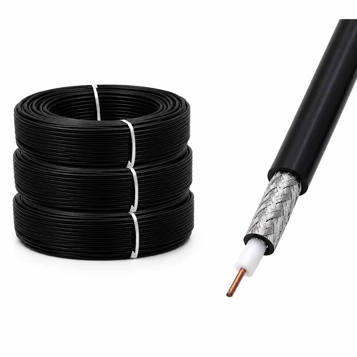
When engineering aerospace, defense, or high-end industrial telemetry systems, selecting the proper high temperature rg cable is a critical decision point that dictates signal integrity and thermal longevity. While our main hub at Worldpeak covers the broad spectrum of RF connectivity solutions available at Worldpeak RF Connectors, this specialized technical brief zooms in on a single, vital sub-point: the performance trade-offs between PTFE and FEP dielectric materials within high temperature rg cable architectures.
Engineers frequently struggle with signal attenuation and dielectric breakdown when systems operate beyond standard thermal thresholds. Understanding how a specific rg cable temperature rating interacts with extrusion mechanics, mechanical stress, and frequency shifts ensures long-term system reliability without over-specifying.
Understanding Thermal Limits and RG Cable Temperature Rating Standards
Standard polyethylene-insulated coaxial lines begin to degrade rapidly once ambient or conductor temperatures exceed 85 degrees Celsius. For high-stress applications in aerospace engine bays, military radar, and industrial automation ovens, a robust high temperature rg cable is non-negotiable.
Under MIL-C-17 military specifications and ISO standards, a certified high temp coaxial cable must maintain structural integrity, low capacitance, and stable characteristic impedance (typically 50 or 75 ohms) under continuous thermal stress.
-
Class 1 Thermal Thresholds: PTFE-based designs commonly withstand continuous operating ranges from -55 degrees Celsius up to +200 degrees Celsius or even +260 degrees Celsius.
-
Class 2 Thermal Thresholds: FEP-insulated variants generally cap out at +200 degrees Celsius, offering a cost-effective alternative for moderately elevated thermal zones.
Reviewing the baseline rg cable temperature rating before deployment prevents catastrophic core melting, dielectric shift, and impedance mismatch during peak load conditions.
Deep Dive: Material Breakdown of PTFE vs. FEP in High Temp Coaxial Cable
The choice of dielectric material directly dictates the mechanical flexibility, electrical loss, and fabrication behavior of a ptfe rg cable versus its fluorinated ethylene propylene counterpart.
| Parameter / Feature | PTFE Insulated RG Cable | FEP Insulated RG Cable |
|
Max Continuous Temperature |
Up to +260 C |
Up to +200 C |
|
Dielectric Constant (Permittivity) |
~2.1 (Low signal attenuation) |
~2.1 - 2.2 (Slightly higher loss) |
|
Mechanical Flexibility |
Moderate (Sintered tape wrap) |
High (Extrudable thermoplastic) |
|
Chemical Resistance |
Extreme (Virtually inert) |
Extremely High |
|
Primary Industrial Use Case |
Aerospace airframes, jet engines |
Medical equipment, industrial sensors |
As demonstrated in the comparison table above, a ptfe rg cable excels in extreme aerospace and military environments where maximum thermal headroom is mandated by mission profiles. Conversely, FEP provides superior melt-extrusion capabilities, allowing manufacturers to achieve tighter concentricity tolerances and seamless jackets over long continuous lengths.
Manufacturing and Quality Control Insights for High Temperature RG Cable
At Worldpeak, ensuring the absolute reliability of every high temperature rg cable batch involves rigorous factory testing protocols that mimic harsh real-world environments.
Extrusion and Sintering Discipline
For PTFE variants, fine powder is paste-extruded and subsequently sintered in high-temperature vertical ovens. Precise thermal profiling during sintering is vital; uneven heating creates micro-voids in the dielectric core, leading to localized voltage breakdown under high RF power.
Spark Testing and Sweep Testing
Every meter of high temp coaxial cable undergoes rigorous spark testing (high-voltage AC/DC breakdown testing) to detect pinholes or jacket imperfections. Furthermore, vector network analyzers (VNAs) perform sweeps up to 18 GHz or higher to verify that the rg cable temperature rating fluctuations do not induce VSWR spikes or return loss degradation.
Real-World Case Application and Avoidance Pitfalls
Case Study: Avionics Test Benches
A major aerospace testing facility experienced recurring intermittent signal loss in engine vibration monitoring rigs. Investigation revealed that standard commercial coaxial lines deployed near exhaust cowls suffered from jacket hardening and conductor migration.
By switching to a specialized high temperature rg cable featuring silver-plated copper conductors and extruded PTFE tape wrapping, the facility eliminated thermal aging failures, achieving a verified MTBF (Mean Time Between Failures) increase of over 300 percent.
Common Engineering Pitfalls to Avoid
-
Ignoring Bend Radius Limits: High temperature rg cable constructions, especially heavy-duty PTFE types, possess stricter minimum bend radii than flexible PVC cables. Over-bending can deform the inner dielectric, permanently altering impedance.
-
Conductor Oxidation Mismatch: Ensure that silver-plated or nickel-plated copper is used consistently. Mismatching connector plating with the cable conductor can trigger galvanic corrosion in humid, high-temperature settings.
-
Overlooking Thermal Derating Curves: Always consult the manufacturer derating curves. Operating a high temp coaxial cable near its absolute maximum temperature ceiling for prolonged cycles reduces overall dielectric lifespan.
Summary and Next Steps
Selecting the ideal high temperature rg cable requires a careful evaluation of thermal ceilings, mechanical flexibility, and dielectric performance standards. By aligning your application parameters with certified military and industrial specifications, you safeguard your RF architecture against premature failure.
To explore our full range of engineered RF solutions and connector compatibility matrices, visit the main portal at Worldpeak RF Connectors. For customized cable assembly inquiries or technical drawing reviews, consult with our engineering support team today.





