 EN

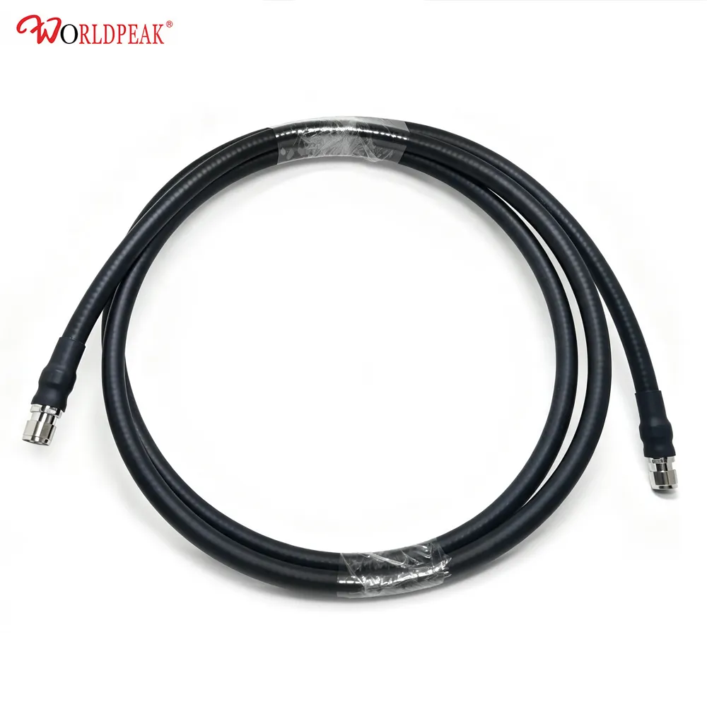
Outdoor wireless networks rarely crash because someone completely forgot to bring a cable. Failure usually slips in when the physical cable run gets pushed aside as a quick, last-minute task. A proper communication feeder cable does far more than bridging the space between a radio unit and an antenna. Everything from exact length, connector direction, and bend radius to waterproofing and testing shifts how smoothly an installation goes.
For engineers and field techs putting up rooftop equipment, cabinet nodes, security setups, or remote wireless links, relying on a custom RF feeder cable assembly changes dozens of tricky field decisions into a single, pre-tested specification.
From a practical RF integration perspective, the real question is never just about finding a random cable on the shelf. The key is asking what must be true at both ends of the run to ensure the outdoor layout stays consistent every single time. That approach brings signal performance, mechanical housing, and field labor into the same practical conversation.
Why Outdoor Cable Routing Always Turns Complicated
A real-world feeder path deals with a lot more than straight distance. A typical run leaves an enclosure through a tight gland, follows a mounting pole or cable tray, rounds sharp corners, hits an antenna bracket, and still needs a clean service loop for maintenance down the road.
At every step along that line, installers have to safeguard the outer jacket, stop tight bends from ruining phase or attenuation, ensure connector access, and block moisture from creeping into sensitive equipment ports.
If a standard off-the-shelf jumper is too long, the leftover coils clog up narrow cabinets or swing around in the wind on a tower. If it comes up short, teams face immediate delay—forced to re-route, add extra adapters, or pause work entirely while waiting for a replacement.
A communication feeder cable carries an equally tough electrical duty. Since it transfers high-frequency signals, impedance stability, insertion loss, and tight connector mating are critical. Acceptable loss limits shift based on link budget, operating frequency, and power level. That is why a neat-looking line is never enough on its own; a solid installation starts with electrical targets and builds a practical route around them.
What Real Customization Means for Field Crews
Custom design does not mean adding rare, overly complex parts. For everyday field operations, customization simply means locking down the variables that normally eat up time on-site. That includes setting the final length, cable type, connector style, gender combinations, right-angle versus straight entry, weather boots, labeling, and packaging.
Specifying a custom communication feeder cable turns open-ended spools into factory-ready jumpers tailor-made for a clear path.
-
Measured Finished Length: Cut along the actual path geometry with smart installation margin, avoiding bulk coils or tight stretches.
-
Tailored Connector Angles: Selected so cables drop naturally out of equipment ports without forcing extreme stress on the interface.
-
Integrated Protection: Matching strain relief, durable outer jacket materials, and gland boots to local cabinet designs.
-
Clear Identification: Factory-applied tags so crews can distinguish multi-band lines before powering up.
Locking in these details cuts down on field guesswork, shield damage, weather exposure, and installation mistakes under tight deadlines.
Building Your Layout from the Connection Endpoints Inward
Map the Physical Ports First
Start with actual interface ports rather than generic interface names. Capture both the radio and antenna port types, housing clearance, preferred drop direction, and whether the line must uncouple easily during maintenance. Photos and quick field sketches prevent ordering a jumper that works on paper but feels awkward during mounting.
Trace the True Cable Path
Measure along the exact paths across brackets, trays, and structural bends. Account for vertical drops, entry glands, and supported service loops. This route-based measurement is far more reliable than guessing with straight-line dimensions. It highlights points where a custom RF feeder cable assembly needs clips, conduit protection, edge guards, or altered paths to avoid pinch points.
Plan Weatherproofing Before Installation Day
Outdoor elements add harsh UV light, driving rain, wind vibration, and rapid thermal cycling to the environment. Choosing a shielded feeder cable makes sense when nearby machinery or co-located antennas generate high electromagnetic noise, but shielding is only part of the puzzle. Connector weatherizing, proper clamping, drip loops, and sealed cabinet entry plates are just as crucial. A pre-built jumper should fit smoothly into the site's grounding scheme instead of replacing proper lightning safeguards.
How Factory Pre-Terminated Lines Save Time
Field termination stays necessary when target route lengths are unknown. However, attached tools, loose connectors, field solder, crimp variations, and tedious testing slow down outdoor work.
With a factory pre-terminated communication feeder cable, installation teams focus their energy on routing, neat clamping, sweep checks, and weather sealing.
Ordering factory-built lines mapped to clear installation drawings simplifies site kitting before truck fleets leave the shop. This process pays off when building multiple identical cell drops or working with strict tower access windows.
Factory assembly gives purchasing teams a clear inspection checkpoint before shipping. Verified loss metrics and sweep tests provide peace of mind before any hardware leaves the floor. Defining target frequency bands and reflection limits within purchase specs ensures every run meets system performance goals.
Quick Checklist for Feeder Path Planning
-
Confirm target frequency range, power handling, impedance, and loss budget.
-
Identify both interface connections, gender combinations, and physical coupling clearances.
-
Measure physical paths carefully to specify length tolerances and loop placements.
-
Account for UV exposure, bracket spacing, wall pass-throughs, and noise shielding requirements.
-
Request custom labeling and factory test records for complete site traceability.
-
Inspect delivered assemblies on the ground before pulling them through mounting hardware.
Separating Cable Specification from Site Commissioning
Opting for custom cables cleans up physical layouts, but it does not skip site commissioning. Once everything is mounted, field techs check joint torque, rubber sealing, cable support tightness, and grounding pads.
Following physical checks, standard RF sweep testing confirms the installed link. Keeping cable specification and live commissioning separate makes sense: factory specifications guarantee what arrives on-site, while field checks prove how the complete system operates after installation.
Building Reliable Wireless Paths with Expert Support
Treating the feeder path as an engineered bridge between equipment and antennas prevents headaches on installation day. Deciding on length, connector geometry, shielding, and labels before production keeps teams off tower structures longer than necessary and avoids improvised fixes inside tight cabinets.
Executing clean, repeatable outdoor layouts relies heavily on a dependable manufacturing partner. WORLDPEAK provides strong supply chain support and specialized custom cable manufacturing for global communication projects.
By matching precise jumper builds to exact site layouts, WORLDPEAK helps engineering teams reduce field labor, maintain strict RF performance standards, and speed up outdoor network rollouts everywhere.





