 EN

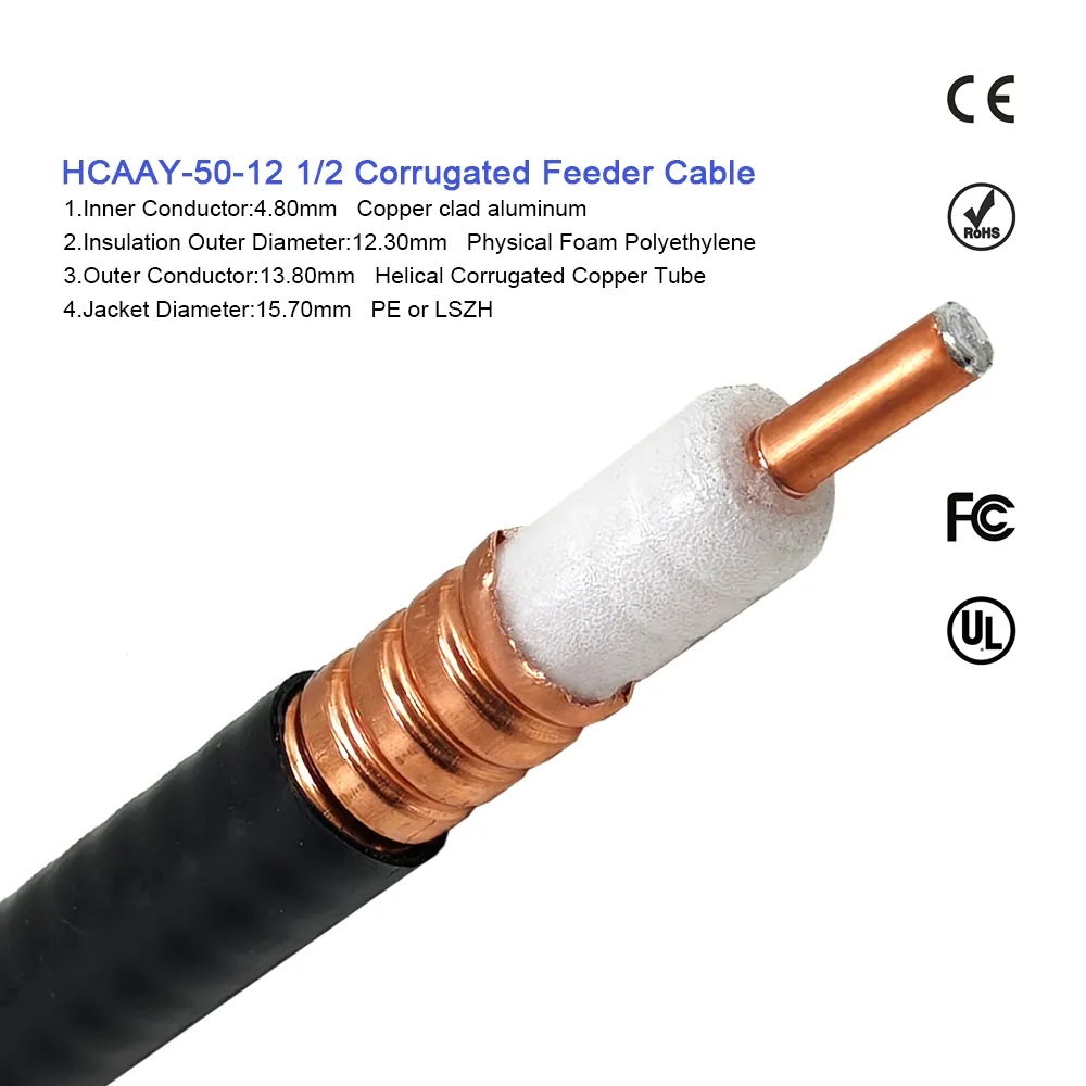
In a telecommunications base station construction project, an RF feeder cable is not simply a length of coaxial wire fitted with standard end connectors. It functions as a critical transmission bridge connecting active remote radio units (RRU), tower-mounted amplifiers (TMA), antenna systems, and lightning surge arrestors. Achieving full compliance with rigorous site acceptance standards requires precision ODM customization. Field conditions—including tight cable tray bend radii, tower clearance limitations, weather exposure, and mixed connector interfaces—rarely match off-the-shelf catalog configurations.
From a telecom procurement and network deployment perspective, relying on generic catalog cables frequently causes costly installation delays and site rework. An improperly specified feeder cable assembly can lead to excessive insertion loss, Passive Intermodulation (PIM) spikes, or moisture ingress at exposed tower interfaces. Partnering with a specialized supplier like WORLDPEAK ensures that every custom rf feeder cable is manufactured to exact engineering drawings, pre-tested on calibrated Vector Network Analyzers (VNA), and labeled for seamless site integration.
Aligning Cable Specifications with Telecom Construction Standards
Base station construction standards are defined by telecom operators, site engineering guidelines, and international cable standards such as IEC 61196-9. However, referencing an international standard alone is insufficient for project release. Engineering leads must explicitly document cable construction details, jacket flame ratings, shielding effectiveness, and connector interface types before manufacturing begins.
An effective ODM customization process turns complex site requirements into a revision-controlled build sheet. This sheet locks down essential physical and electrical parameters:
-
Exact Feeder Cable Size and Geometry: Matching 1/2 in, 7/8 in, or 1-1/4 in corrugated coaxial cable to link-budget attenuation limits and routing tray geometries.
-
Interface and Gender Precision: Specifying 7/16 DIN, 4.3-10, or N-Type connectors with straight or right-angle exits tailored to radio equipment ports.
-
Jacket Material Compliance: Selecting UV-resistant Polyethylene (PE) for outdoor tower runs or Low-Smoke Zero-Halogen (LSZH) compounds for indoor equipment shelters.
-
Traceable Acceptance Protocols: Requiring 100% pre-shipment testing for VSWR, return loss, and insertion loss across target frequency bands (e.g., 698 MHz to 3800 MHz).
Technical Comparison: Standard Catalog vs. Custom ODM Feeder Cable Assemblies
Selecting the right rf feeder cable requires comparing mechanical flexibility, attenuation levels, shielding performance, and installation efficiency. The table below outlines key differences between standard off-the-shelf products and tailored ODM customization solutions.
| Specification Parameter | Standard Catalog Feeder Cable | Custom ODM Feeder Cable Assembly |
| Cable Length & Tolerance | Fixed increment lengths (e.g., 5m, 10m) | Custom exact length (mm precision) to eliminate site slack |
| Connector Configurations | Standard male/female pairs | Custom mixed interfaces (e.g., 4.3-10 Male to 7/16 DIN Female) |
| Weatherproofing Options | Separate tape or boot kits required | Integrated factory cold-shrink boots or molded strain relief |
| VSWR / Return Loss Testing | Statistical batch sampling | 100% individual VNA sweep test report included per lot |
| PIM Performance Rating | Standard catalog rating (<= -150 dBc) | Guaranteed Low-PIM rating (<= -160 dBc or -165 dBc) |
| Site Labeling & Packaging | Generic part numbering | Custom site-specific tagging and sequential route labels |
Five Essential Customization Controls for Base Station Installation
Executing a successful base station deployment depends on controlling five core engineering parameters during the ODM customization phase:
1. Cable Sizing and Routing Allowance
While larger diameter feeder cables reduce signal loss over long vertical tower runs, their rigid bend radii can complicate cabinet entry. ODM customization balances attenuation targets against routing constraints, ensuring the specified feeder cable fits cable ladders without exceeding maximum bending limits.
2. Connector Interface and Clocking Orientation
Connector mismatches waste time during site installation. Specifying exact interface series (such as 4.3-10 or 7/16 DIN) and pre-orienting right-angle connectors minimizes the need for inline adapters. Fewer adapters directly reduce PIM generation points and lower weatherproofing workload for field technicians.
3. Outdoor Jacket and Weatherproofing Seals
Exposed tower jumper runs must withstand severe UV exposure, temperature cycling, and wind-driven rain. Defining factory-installed cold-shrink boots or dual-wall adhesive sealing ensures the completed rf feeder cable interface maintains IP67 or IP68 ingress protection over a long service life.
4. Precision Length Control and Route Tagging
Custom feeder cable assemblies delivered to exact site drawing lengths prevent messy slack loops on cable trays. Durable, UV-resistant labels marked with project identifiers allow installation crews to match each jumper to its designated sector and radio port immediately upon arrival.
5. Factory Electrical Sweep Evidence
Every custom rf feeder cable must undergo rigorous factory verification prior to shipment. Providing traceable insertion loss and VSWR sweep test records verified across 5G NR and LTE frequency bands ensures total compliance with operator acceptance criteria before site hoisting begins.
The ODM Manufacturing and Quality Verification Workflow
A structured ODM customization workflow eliminates supply chain ambiguity and protects signal integrity from raw cable preparation through site commissioning.
Key ODM Workflow Steps:
-
Design Input Freeze: Review route CAD drawings, radio port specifications, required attenuation limits, and environmental conditions.
-
First-Article Approval: Build physical prototype samples for tight-tolerance or non-standard configurations to confirm mechanical fit and handling.
-
Automated Production & Assembly: Strip corrugated copper outer conductors and terminate connectors using calibrated automated tooling to ensure low contact resistance and stable PIM.
-
100% Electrical Sweep Verification: Test every completed feeder cable assembly on calibrated Vector Network Analyzers across specified operating bands.
-
Traceable Packaging & Shipping: Package assemblies with site-specific identification tags and serialized sweep test records attached to each shipment.
Site Acceptance Checklist for RF Feeder Cable Assemblies
Before commissioning a newly installed base station sector, field quality engineers should execute this standard verification checklist:
-
Verify Physical Cable Construction: Confirm that the delivered feeder cable outer conductor, diameter, and jacket material match approved engineering drawings.
-
Inspect Connector Interfaces and Torque: Check that 4.3-10 or 7/16 DIN interfaces are clean, undamaged, and torqued to specified manufacturer limits using calibrated wrenches.
-
Review Factory Sweep Test Reports: Ensure individual VSWR and insertion loss test certificates are present and match the serial numbers tagged on the rf feeder cable.
-
Examine Weatherproofing Integrity: Confirm that cold-shrink boots or weather-sealing tape systems fully enclose the mated connector junction and outer jacket boundary.
-
Partner with an Industry Leader: Working directly with an established manufacturer like WORLDPEAK gives telecom operators access to fully custom, factory-tested feeder cable assemblies designed to meet demanding global construction standards.





