 EN

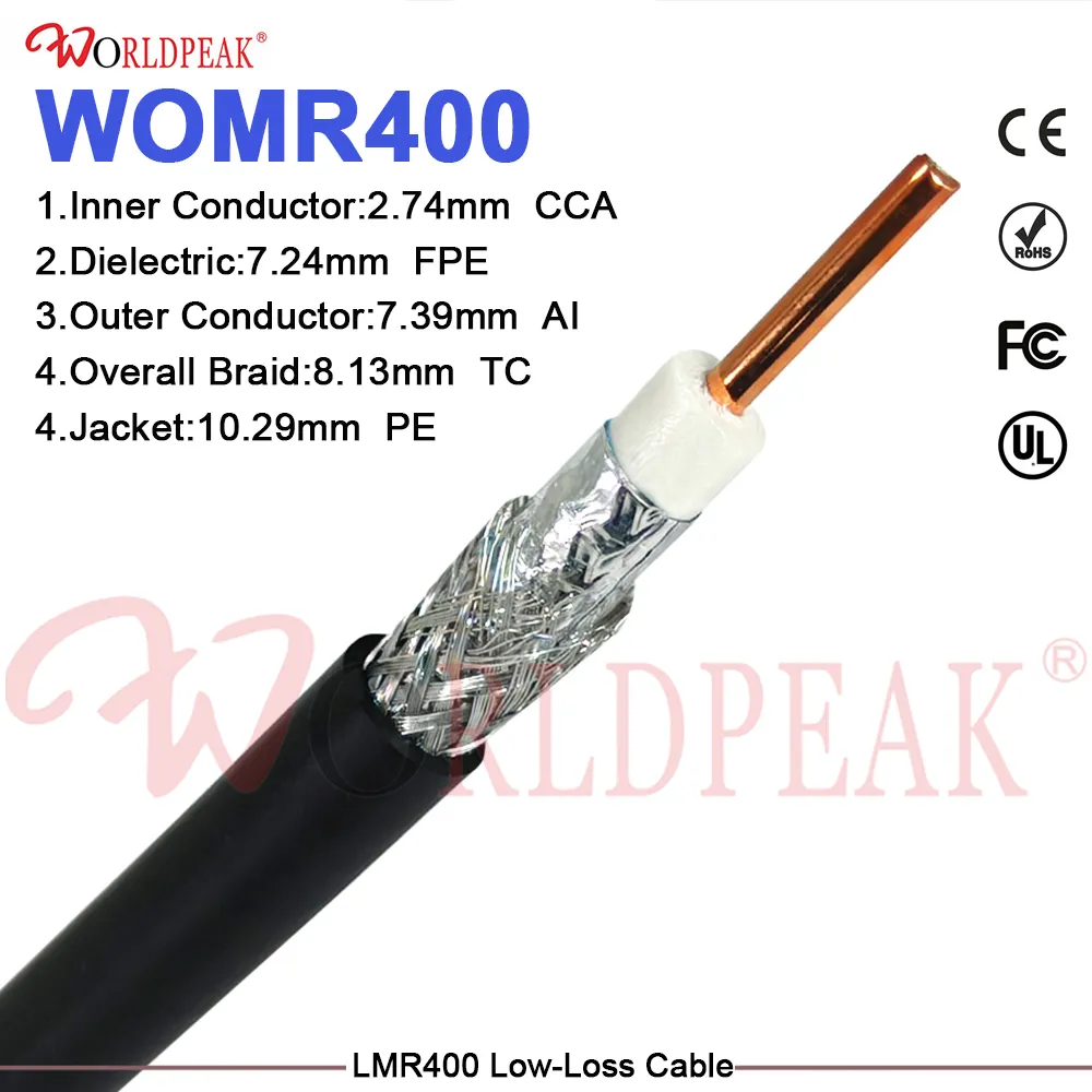
Outdoor communication sites rarely experience signal failure because a component looked incorrect on a purchase order. System degradation occurs when standard hardware designed for controlled indoor environments encounters severe ultraviolet radiation, wind-driven rain, continuous thermal cycling, mechanical vibration, and tight routing constraints. Specifying an outdoor coaxial cable as a unified factory assembly—rather than cutting bulk reel cable and installing connectors on site—ensures long-term link reliability.
For OEM engineering teams, evaluating weather resistance extends beyond basic jacket selection. A complete outdoor coaxial cable assembly must align with working frequency bands, characteristic impedance targets, physical routing paths, connector interface families, ingress sealing methods, and incoming quality inspection standards. While incorporating a low loss coaxial cable provides necessary RF margin, low attenuation alone cannot compensate for a poorly sealed connector interface or an unrated cable entry point.
Evaluating Outdoor Failure Mechanisms Beyond Generic Categories
Outdoor communication deployments present distinct environmental stress profiles. Rooftop cellular radios, highway camera networks, coastal antenna feeds, and industrial wireless enclosures impose unique mechanical and thermal demands. Documenting physical routing, mechanical contact points, and termination environments helps prevent premature field failures.
Primary environmental stress factors include:
-
Solar Radiation and Thermal Cycling: Sustained UV exposure degrades standard PVC jackets, causing cracking and moisture ingress. Extreme temperature shifts induce expansion and contraction across dissimilar assembly materials, stressing solder joints and crimp sleeves.
-
Water Migration Paths: Condensation, standing water, and capillary action pull moisture through unsealed connector threads, cable entry glands, and jacket breaches, raising insertion loss and degrading VSWR.
-
Mechanical Stress and Flexure: Wind-induced tower vibration, tight cabinet turns, and improper support clamp spacing lead to conductor fatigue and dielectric deformation over time.
-
Electrical Link Margin: Total signal attenuation depends on working frequency, allowable system loss budgets, VSWR limits, and the total number of interconnect transitions.
Replacing vague requests for "weatherproof coax" with precise application requirements enables suppliers to optimize assembly construction around site-specific risks. High UV environments call for UV-stabilized PE or LSZH jackets and molded strain relief boots. Cramped enclosure routes require right-angle connector orientations and high-flex conductor geometries to preserve dielectric concentricity.
Translating Site Conditions into Technical OEM Specifications
An effective OEM cable specification establishes clear boundaries between fixed design requirements and configurable supplier options. Locking critical parameters upfront prevents field modifications during installation.
When specifying a low loss coaxial cable, engineers must define the operating frequency along with maximum insertion loss allocations. Published attenuation charts reflect nominal bulk cable performance under laboratory conditions; actual field loss varies based on connector count, assembly length, routing geometry, and termination execution.
Service frequency also dictates component selection. Systems requiring frequent disconnection for testing or maintenance demand ruggedized connector coupling nuts, gold-plated contacts, and protective dust caps to prevent interface wear during routine servicing.
Connector Integration as an Environmental Barrier
Connectors form the primary environmental seal for an outdoor coaxial cable. A fully integrated OEM coaxial cable assembly combines compatible interfaces, controlled termination methods, and engineered sealing to guard against environmental ingress. Sealing practices suitable for sheltered indoor cabinets often fail when exposed to direct driving rain or thermal pressure differentials.
| Environmental Parameter | Standard Indoor Assembly | Custom OEM Outdoor Assembly |
|---|---|---|
| Jacket Compound | Flexible PVC (standard indoor grade) | UV-stabilized Polyethylene (PE) or LSZH |
| Ingress Protection | Unsealed or IP50 open interface | IP67 / IP68 internal O-rings & weatherproofing boots |
| Thermal Operating Range | -20°C to +70°C | -40°C to +85°C extended thermal range |
| Mechanical Strain Relief | Single-wall heat shrink sleeve | Heavy-duty dual-wall adhesive-lined shrink tubing |
| RF Verification | Visual check or basic continuity | 100% VNA sweep for Insertion Loss & VSWR |
Evaluating the complete assembly as a unified electrical and mechanical system ensures that connector joints do not become weak points in rugged outdoor environments.
Verifying RF Performance via Traceable Test Standards
Custom OEM assemblies require observable electrical acceptance criteria to verify link integrity. Conducting Vector Network Analyzer (VNA) sweep testing across the target frequency band confirms that insertion loss and Return Loss (VSWR) meet design specifications before shipment.
Pre-shipment VNA sweep data provides traceable verification for high-reliability deployments, including cellular infrastructure, defense communication links, and municipal wireless networks. WORLDPEAK provides complete insertion loss and VSWR sweep test documentation with custom cable orders, validating electrical performance prior to field installation. Matching individual test reports to cable serial numbers ensures full quality traceability across production batches.
Streamlining Customization for Repeatable Production
Ensuring manufacturing consistency across repeat production runs requires a unified technical specification sheet. Documenting core assembly parameters eliminates ambiguity across engineering, procurement, and quality control teams.
Key details to include in a configuration record:
-
Cable Architecture: Outer conductor type (braid, foil, or corrugated), dielectric material, and center conductor plating.
-
Assembly Length & Tolerances: Tip-to-tip dimensions and acceptable manufacturing length tolerances.
-
Connector Configurations: Connector family, gender, polarity, body plating (e.g., Tri-Metal/White Bronze), and body orientation (straight or right-angle).
-
Environmental Sealing & Accessories: Adhesive-lined heat shrink, silicone O-ring seals, protective dust caps, and custom labeling formats.
-
Testing Scope & Revisions: Frequency sweep limits, VSWR thresholds, and official drawing revision control numbers.
Leveraging WORLDPEAK's custom manufacturing program allows OEMs to configure custom lengths, mixed connector combinations, and specialized jacket materials without sacrificing lead times or quality standards.
Technical Qualification Checklist for Outdoor OEM Programs
-
Document Site Exposure: Map environmental risks, thermal limits, UV levels, physical routing constraints, and cabinet entry points.
-
Define Electrical Budget: Establish system-level attenuation limits and VSWR thresholds for the complete outdoor coaxial cable run.
-
Select Compatible Interfaces: Specify connector families, contact plating, sealing gaskets, and strain relief parameters.
-
Lock Engineering Drawings: Issue controlled configuration drawings detailing length, materials, labeling, and revision numbers.
-
Mandate Factory Testing: Require pre-shipment VNA sweep documentation for insertion loss and VSWR compliance.
-
Validate First Articles: Review First Article Inspection (FAI) samples prior to launching full-scale mass production.
Conclusion: Engineering Complete Transmission Paths
Optimizing an outdoor communication link requires evaluating physical exposure, mechanical constraints, and electrical performance together. When link budget margin is the main constraint, selecting a certified low loss coaxial cable with verified attenuation data takes priority. When environmental exposure or cramped routing governs the installation, jacket selection, connector sealing, and strain relief become critical. Partnering with a specialized OEM manufacturer ensures that every outdoor coaxial cable assembly arrives fully tested, compliant with design specifications, and ready for reliable long-term field deployment.





