 EN

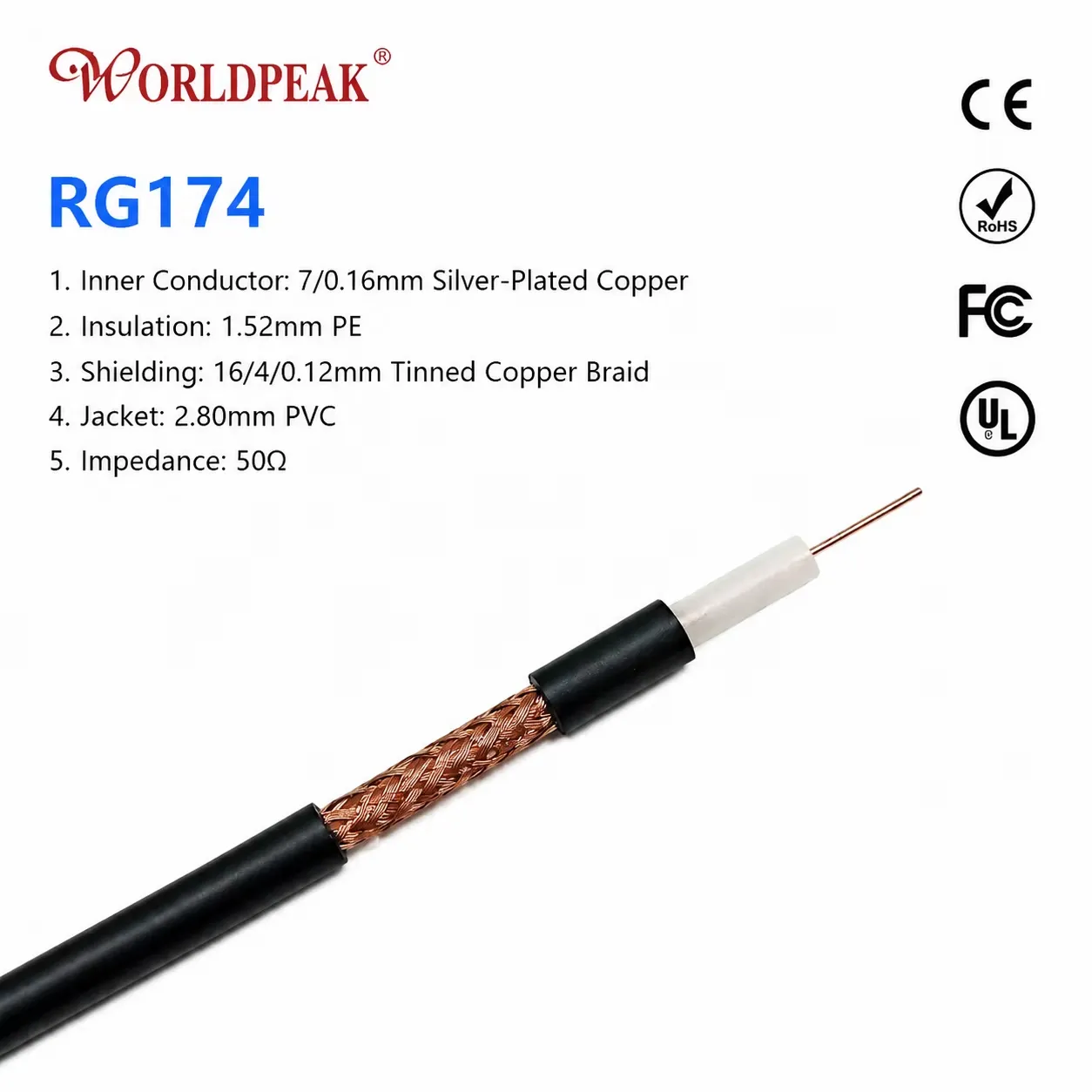
When an RF communications system operates in non-standard or highly specialized frequency bands, relying on off-the-shelf coaxial hardware can introduce unpredictable signal degradation. A standard rg cable may look fully functional on the surface, yet subtle variations in its dielectric compound, braid shielding coverage, jacket material, and connector interface directly dictate whether the assembled signal path behaves consistently. For OEM engineering teams building specialized radios, IoT sensing equipment, test fixtures, and military-grade wireless devices, performing targeted OEM rg cable modification guarantees long-term phase stability and minimal attenuation across non-standard operating frequencies.
As an experienced RF systems engineer will confirm, modifying a custom rg cable must start with the system operating bandwidth and signal loss budget rather than physical cable dimensions alone. A standard rg58 coaxial cable assembly might perform adequately during bench testing at lower frequencies, but can exhibit severe reflection spikes, mechanical fatigue, or insertion loss when subjected to tight bend radii, temperature fluctuations, or elevated frequency ranges. Partnering with a specialized manufacturer like
Why Special-Frequency Environments Require Custom Cable Engineering
The standard designation assigned to an rg cable describes a generic physical construction family rather than a guaranteed electrical performance spec across all frequency bands. Cable outer dimensions, center conductor plating, dielectric foaming ratios, and braid shielding density vary significantly between suppliers offering products under the same designation. For instance, a standard rg58 coaxial cable is universally recognized as a 50-ohm interconnect, yet actual frequency limits, voltage breakdown ratings, and temperature tolerances differ between commercial-grade and military-specification variants.
Key Technical Factors Influencing Special-Frequency Performance:
-
Impedance Continuity: Tolerances in dielectric extrusion affect nominal impedance, causing unwanted impedance mismatches at higher frequencies.
-
Shielding Effectiveness: Single-braid construction in a basic rg cable allows high RF leakage in dense electromagnetic interference (EMI) environments.
-
Dielectric Velocity Factor: Foamed versus solid PTFE/PE dielectrics change phase stability when the rg58 coaxial cable experiences ambient thermal cycling.
-
Connector Interface Discontinuities: Improper crimp ferrule seating or mismatched connector pin geometries create localized VSWR spikes at non-standard band limits.
Executing a structured OEM rg cable modification addresses these vulnerability points by tailoring dielectric formulations, adding secondary foil shielding layers, and locking down precision connector termination processes.
Technical Comparison: RG Cable Modifications vs. Standard Catalog Specs
Selecting and modifying an rg cable requires comparing physical dielectric construction, shielding layers, attenuation limits, and environmental tolerances. The table below outlines how custom OEM rg cable modification options upgrade standard rg58 coaxial cable configurations for demanding RF environments.
| Performance Parameter | Standard Catalog RG58 | Modified OEM RG58 Cable | Double-Shielded Custom RG Cable | Precision Low-Loss RG Cable |
| Center Conductor | Bare Copper / Tinned Copper | Silver-Plated Copper | Silver-Plated Copper Clad Steel | Solid Silver-Plated Copper |
| Dielectric Material | Solid Polyethylene (PE) | High-Temp PTFE / Foamed PE | Solid PTFE | Micro-Porous PTFE |
| Shielding Stack | Single Bare Copper Braid (>=85%) | Double Silver-Plated Braid (>=95%) | Aluminum Foil + Silver Braid (>=98%) | Dual Silver Braid + Tape Wrap (99%) |
| Outer Jacket Compound | Commercial PVC | High-Temp FEP / LSZH | UV-Resistant Polyurethane (PUR) | Fluoropolymer (FEP) |
| Velocity of Propagation | 66% | 70% – 82% | 70% | 80% – 85% |
| Upper Frequency Limit | Up to 1 GHz | Up to 3 GHz | Up to 5 GHz | Up to 6 GHz – 8 GHz |
| VSWR at Band Limits | Typical <= 1.35 | Controlled <= 1.15 | Controlled <= 1.20 | Precision <= 1.12 |
Core Engineering Levers in Custom RG Cable Modification
Tailoring a flexible rg cable for non-standard frequencies involves three primary engineering levers that directly control RF transmission quality and mechanical longevity:
1. Conductor and Dielectric Customization
Maintaining a uniform 50-ohm impedance profile throughout a modified rg58 coaxial cable requires tight tolerance control over center conductor concentricity and dielectric extrusion. Upgrading to silver-plated copper conductors lowers skin-effect losses at elevated frequencies, while high-density PTFE dielectrics maintain thermal stability under high RF power levels.
2. Shielding Enhancements and Protective Jackets
Specialized wireless environments often expose an rg cable to strong external interference or harsh ambient conditions. Incorporating a dual-layer braid or bonding an aluminum foil shield directly to the dielectric increases shielding effectiveness beyond 90 dB. Selecting a low-smoke zero-halogen (LSZH) or Fluorinated Ethylene Propylene (FEP) jacket protects the underlying rg58 coaxial cable from chemical exposure, UV degradation, and mechanical abrasion.
3. Precision Connector Integration and Strain Relief
A custom rg cable is only as reliable as its end terminations. Specifying precision SMA, N-Type, BNC, or TNC connectors with custom crimp ferrules ensures minimal return loss. Applying dual-wall adhesive heat-shrink boots provides robust strain relief, shielding the vulnerable cable-to-connector transition zone against mechanical fatigue and moisture ingress during field operation.
Step-by-Step OEM Qualification and Verification Workflow
To guarantee that a modified rg58 coaxial cable satisfies system loss budgets and operational lifetimes, engineering teams must follow a disciplined qualification sequence:
-
Application Requirements Freeze: Define target operating frequency, bandwidth, power handling, maximum acceptable VSWR, and total insertion loss budget.
-
Mechanical Routing Assessment: Establish minimum dynamic and static bend radii, connector orientation (straight vs. right-angle exit), panel cutout dimensions, and enclosure clearance constraints.
-
Prototype Fabrication and Verification: Build revision-controlled rg cable samples using production-intent crimp tooling, automated stripping equipment, and gold-plated center pins.
-
Comprehensive Electrical Sweep Testing: Perform 100% S-parameter (VSWR and Return Loss) testing on a calibrated Vector Network Analyzer (VNA) across the complete frequency range.
-
Pilot Production Approval: Issue formal documentation specifying BOM part numbers, drawing revision levels, visual inspection criteria, and packaging standards before releasing volume manufacturing.
Checklist for Ordering Modified RG Cable Assemblies
Before submitting an engineering inquiry for a custom rg cable or modified rg58 coaxial cable build, complete the following technical checklist:
-
State Exact Frequency and Impedance: Specify operating band limits and confirm nominal system impedance (50 Ohm).
-
Provide Complete Mechanical Envelope: Define finished assembly length tolerances, reference planes, and minimum bend radii restrictions.
-
Select Appropriate Jacket and Shielding: Detail whether the rg cable requires UV resistance, LSZH compliance, or multi-layer braid shielding.
-
Specify Connector Interfaces and Orientations: Clarify series, gender, polarity, body plating (nickel vs. tri-metal), and strain-relief boot style.
-
Partner with an Established RF Manufacturer: Work directly with
WORLDPEAK





