 EN

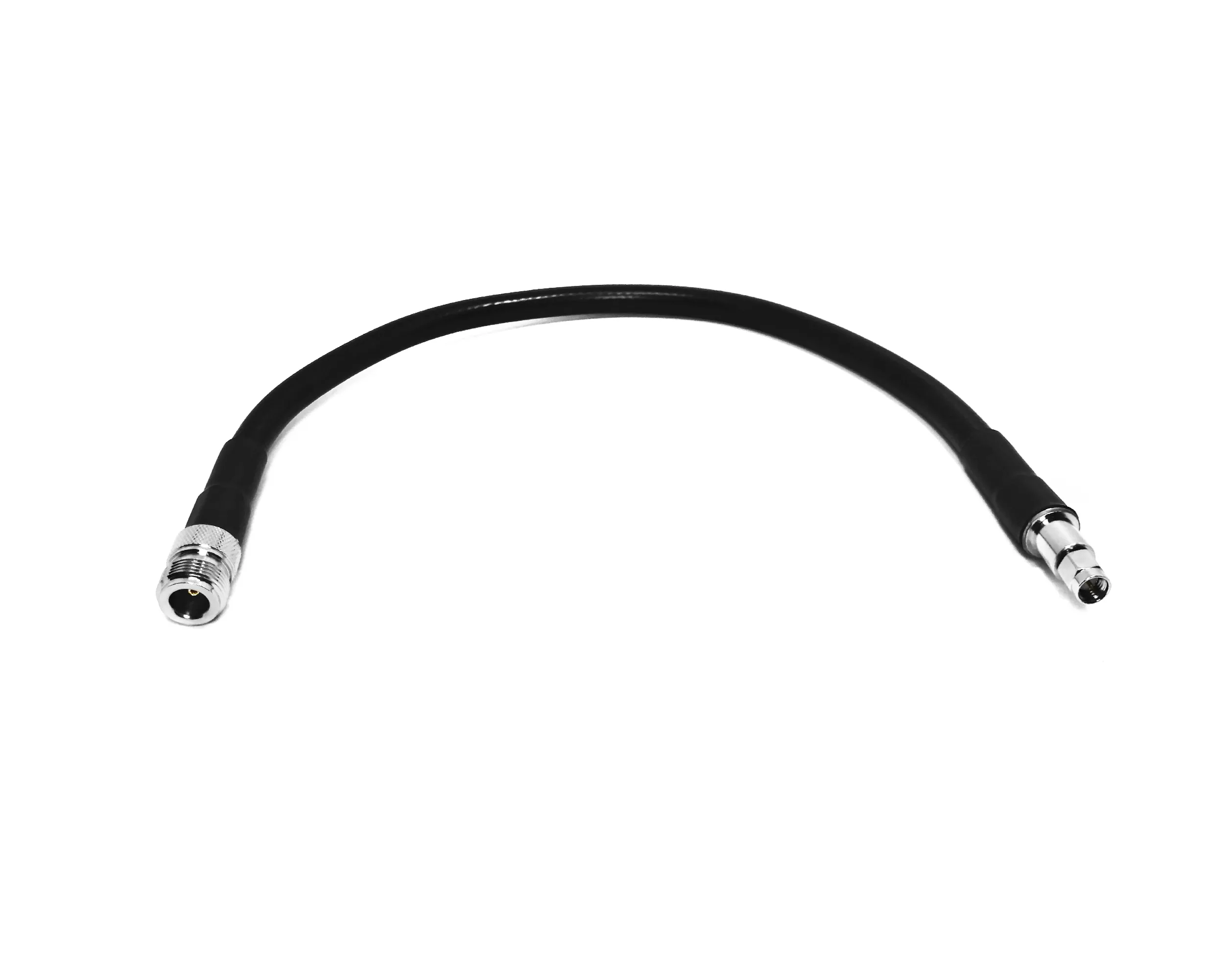
In a high-vibration mobile RF application—such as rail transit gateways, commercial fleet telematics, emergency vehicles, and heavy agricultural machinery—coaxial interconnects experience continuous mechanical stress. Unlike static indoor base stations, mobile equipment subjects every tnc connector to engine harmonics, chassis shock, thermal expansion, and constant cable flexing. If an OEM design relies on unverified catalog components or hand-tightened interfaces, small mechanical movements can lead to intermittent RF signal loss, unexpected VSWR spikes, and physical connector backing-off.
A threaded tnc connector offers superior anti-vibration security compared to bayonet-style BNC interfaces. However, thread engagement alone cannot solve every moving-equipment challenge. Ensuring long-term signal integrity in a mobile RF application requires optimizing the entire interconnect assembly: matching the tnc male connector geometry to the coax jacket, specifying anti-rotation panel cutouts, controlling mating torque, and providing robust cable strain relief. Partnering with an experienced manufacturer like
Why Vibration Changes the Connector Selection Problem
The physical load path in a mobile RF application originates at the vehicle chassis, transfers through enclosure mounting brackets, and terminates at the soldered or crimped contact interface of the tnc male connector. Without proper strain relief, unsupported cable mass acts as a lever arm, fatigue-stressing the center pin contact and loosening the threaded coupling nut.
Primary Failure Modes in High-Vibration Environments:
-
Coupling Back-Off: Inadequate mating torque allows thread vibration to back off the tnc connector coupling nut over time.
-
Fretting Corrosion: Micro-movements at the center contact interface cause plating wear, generating non-linear resistance and microphonic noise.
-
Cable Termination Fatigue: Cyclic flexing directly behind the tnc male connector ferrule cracks the outer braid wire strands or breaks center conductor solder joints.
-
Panel Rotation: Smooth round panel cutouts allow the tnc connector bulkhead body to rotate during vehicle movement, twisting internal pigtail leads.
Addressing these failure modes requires moving beyond generic part numbers and specifying a complete, revision-controlled OEM tnc connector solution tailored to the vehicle's dynamic load path.
Technical Comparison: Standard TNC vs. High-Vibration Mobile TNC Configurations
Selecting the correct tnc connector for a mobile RF application requires comparing housing materials, coupling nut retention features, dielectric seating, and environmental IP sealing. The table below outlines key engineering distinctions across standard and heavy-duty tnc male connector designs.
| Engineering Parameter | Standard Commercial TNC | High-Vibration Mobile TNC | Heavy-Duty Bulkhead TNC Female |
| Housing Base Material | Machined Brass | High-Tensile Machined Brass / SS | Stainless Steel / Heavy Brass |
| Coupling Mechanism | Standard Threaded Coupling | Thread-Lock / Anti-Vibration Tooth | Bulkhead Hex Nut + Lock Washer |
| Center Contact Plating | 3-5 uin Gold Plating | 30-50 uin Hard Gold Plating | 30 uin Hard Gold Plating |
| Gasket & Weather Sealing | Standard Silicone O-Ring | Dual Internal O-Rings (IP67/IP68) | Hermetic / Rear Panel O-Ring |
| Frequency Rating | DC to 6 GHz / 11 GHz | DC to 11 GHz | DC to 11 GHz |
| Max Mating Torque | 0.46–0.68 Nm (4–6 in-lbs) | 0.9–1.4 Nm (8–12 in-lbs) | 1.4–2.0 Nm (12–18 in-lbs) |
| Vibration Tolerance | Standard Bench Profile | MIL-STD-202 Method 204 (10-2000Hz) | MIL-STD-202 Method 214 (Random) |
Four Pillars of High-Vibration TNC Connector Engineering
Designing a robust tnc connector assembly for a mobile RF application requires integrating four critical mechanical and electrical controls:
1. Anti-Rotation Panel Mounting
When installing a bulkhead tnc connector on a vehicle enclosure, specify D-shaped or double-D panel cutouts paired with star lock washers. This prevents the connector housing from spinning when technicians attach a external tnc male connector in the field.
2. Precision Crimp & Cable Matching
A tnc male connector must match the exact dimensions of the selected coaxial cable (e.g., LMR-240, RG-58, or RG-223). Utilizing calibrated crimp dies ensures that the ferrule compresses the outer braid uniformly without crushing the dielectric core or inducing impedance discontinuities.
3. Controlled Mating Torque Protocols
Relying on hand-tightening in a mobile RF application invites failure. Work instructions must specify exact torque values (typically 8 to 12 in-lbs for brass interfaces) applied with a calibrated torque wrench to lock the tnc connector threads securely.
4. External Cable Support and Strain Relief
The single most effective defense against vibration fatigue is securing the coax cable within 50 mm to 100 mm of the tnc male connector exit. Utilizing heavy-duty dual-wall adhesive heat-shrink boots shields the termination zone from moisture ingress and mechanical strain.
Step-by-Step OEM Validation Protocol for Mobile RF Assemblies
Before releasing a custom tnc connector design for mass production, OEM engineering teams should validate physical prototypes against a structured qualification protocol:
-
Dimensional and Interface Verification: Check thread pitch, pin depth, and center socket alignment against revision-controlled engineering drawings.
-
Pre-Test S-Parameter Baseline: Measure Return Loss (VSWR) and Insertion Loss across the target frequency band on a calibrated Vector Network Analyzer (VNA).
-
Random Vibration and Mechanical Shock Exposure: Subject the fully mated tnc male connector assembly (including panel mounts and clamped cable runs) to MIL-STD-202 vibration profiles.
-
Post-Vibration Electrical Sweep: Re-test S-parameters to confirm zero performance degradation or intermittent signal loss.
-
Micro-Sectioning Inspection: Inspect crimp ferrules and center contact crimps under magnification to verify mechanical retention and material integrity.
OEM Checklist for Sourcing Mobile TNC Connectors
Before submitting an RFQ for a high-vibration mobile RF application, complete this technical checklist:
-
Specify Exact Cable Type and Construction: Define jacket OD, braid coverage percentage, and center conductor type for the tnc male connector.
-
Detail Environmental Protection Requirements: State whether IP67, IP68, or salt-spray corrosion resistance is required for the assembled tnc connector.
-
Lock Down Torque Specifications and Tooling: Ensure production lines are equipped with calibrated torque wrenches for tnc male connector coupling.
-
Incorporate Cable Support Guidance: Document cable tie-down locations on assembly drawings to limit vibration leverage.
-
Partner with a Qualified Manufacturer: Working directly with an established RF supplier like
WORLDPEAK





