 EN

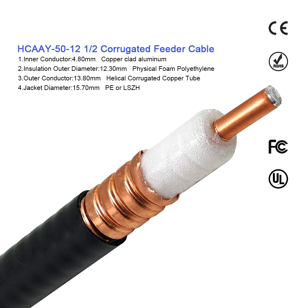
When an RF communications system misses its performance targets, the breakdown is rarely caused by a single component failure. Instead, it is usually the compound effect of micro-mismatches across connector interfaces, custom cable assemblies, passive rf devices, and uncalibrated acceptance testing. For an OEM engineering team, coordinating these interconnected elements across multiple suppliers creates long delays, confusing drawing revisions, and high quality-control overhead. Partnering with a dedicated one-stop OEM service integrates all critical rf components into a unified, traceable manufacturing workflow.
From an international procurement perspective, the value of a one-stop OEM service extends far beyond vendor consolidation. It creates a seamless bridge between the RF system engineer designing the signal path and the purchasing agent managing production lead times, batch consistency, and lot-level inspection. Partnering with an experienced manufacturer like
Start with the Complete Signal Path, Not a Line-Item Purchase Order
A traditional procurement request treats rf components—such as RF connectors, adapters, passive rf devices, and coaxial jumpers—as standalone commodity line items. However, an RF circuit views them as a single continuous transmission medium. Every mechanical transition introduces localized capacitance and inductance that can impair system-level Voltage Standing Wave Ratio (VSWR) and insertion loss.
Essential Signal Path Mapping Inputs:
-
Interface Compatibility: Verify exact series, gender, polarity, and body threading across all mating rf components.
-
Operating Bandwidth: Ensure all inline passive rf devices and interconnects operate with consistent frequency headroom (e.g., DC to 6 GHz or DC to 18 GHz).
-
Physical Routing Envelope: Identify tight clearance zones requiring right-angle exits, bulkhead panels, or high-flex coaxial constructions.
-
Environmental Exposure: Specify IP sealing ratings, operating temperature ranges, and vibration limits for all exposed rf components.
By mapping the signal path before issuing an RFQ, engineering teams enable a one-stop OEM service to evaluate structural transitions as a unified RF channel rather than processing disconnected catalog parts.
What a True One-Stop OEM Workflow Integrates
An expert one-stop OEM service coordinates four critical technical workstreams to prevent performance mismatches across production lots:
When systems integrate multiple connector series—such as SMA, N-Type, BNC, and TNC—a consolidated one-stop OEM service verifies that tolerances across all rf components meet international standards (such as IEC 61169) before releasing volume production.
Technical Comparison: Sourcing Dispersed RF Components vs. Integrated OEM Service
To highlight the operational advantages of a one-stop OEM service, the table below compares traditional multi-vendor sourcing against an integrated OEM manufacturing model.
| Evaluation Parameter | Multi-Vendor Sourcing | Integrated One-Stop OEM Service |
| Supply Chain Complexity | High (5–10 separate POs, drawings, and vendors) | Low (1 single contact for all rf components) |
| Interface Compatibility | Risk of cumulative mechanical/electrical mismatches | Verified interface alignment across all rf components |
| Test Plan Consistency | Fragmented test setups and non-standardized reports | Unified 100% VNA sweep testing and S-parameter data |
| Revision Control | High risk of revision drift across suppliers | Locked baseline drawing package and BOM traceability |
| Lead Time & Shipping | Asynchronous deliveries and delayed assembly lines | Synchronized production and bundled lot deliveries |
| Quality Accountability | Frequent vendor dispute over failure attribution | Single-source quality guarantee for all rf components |
Incorporating Passive RF Devices into the OEM Integration Plan
While active radio modules receive significant engineering attention during initial product design, passive rf devices—including inline attenuators, directional couplers, power dividers, and RF terminations—dictate system reliability. Inserting an unverified adapter or low-grade passive device to bridge a supply chain gap can introduce unwanted reflection spikes and loss.
Key Verification Rules for Passive RF Devices:
-
Eliminate Unnecessary Adapters: Use custom direct-interface cable assemblies built by your one-stop OEM service to eliminate unnecessary inline adaptors.
-
Verify Power Handling Ratings: Confirm that all passive rf devices maintain stable dielectric performance under continuous peak RF power conditions.
-
Harmonize Material & Plating Specifications: Match body plating (e.g., gold center pins and tri-metal body plating) across all rf components to prevent galvanic corrosion and passive intermodulation (PIM).
Step-by-Step Engineering-to-Procurement Handoff Workflow
To ensure a seamless transition from prototype testing to high-volume production, an engineering team should execute a structured handoff with their one-stop OEM service provider:
-
System Blueprint Submission: Provide a detailed RF signal path diagram outlining all rf components, cable runs, and panel boundaries.
-
Acceptance Criteria Definition: Establish explicit sweep test ranges, maximum allowable VSWR thresholds, and acceptable insertion loss limits.
-
First-Article Inspection (FAI): Request labeled prototype samples manufactured with production-intent tooling and verified on calibrated Network Analyzers.
-
Drawing & BOM Lock: Issue formal approval locking drawing revision numbers, cable length tolerances, and material specifications for all rf components.
-
Volume Release Matrix: Release production orders using a single, unified BOM supported by full lot-level traceability from your one-stop OEM service partner.
Practical Checklist for Evaluating a One-Stop OEM Partner
Before selecting a manufacturing partner for your integrated rf components, evaluate their technical capabilities against this operational checklist:
-
Does the Supplier Offer Full-Spectrum Interface Support?: Verify capability across standard, subminiature, and high-frequency connector series.
-
Are Electrical Sweep Reports Standard?: Confirm that pre-shipment insertion-loss and VSWR sweep test documentation can be included with shipped rf components.
-
Is Revision Control Enforced at Every Stage?: Ensure all drawings, custom cable assemblies, and passive rf devices carry locked revision identifiers tied to your purchase order.
-
Does the Partner Offer In-House Cable Fabrication?: Verify that automated stripping, crimping, and micro-soldering are performed under certified quality management systems.
-
Work with an Industry Leader: Partnering with an established manufacturer like
WORLDPEAK
By replacing fragmented multi-vendor purchasing with a structured one-stop OEM service, equipment manufacturers eliminate technical ambiguities, protect signal integrity, and build a reliable supply chain ready for global market expansion.





