 EN

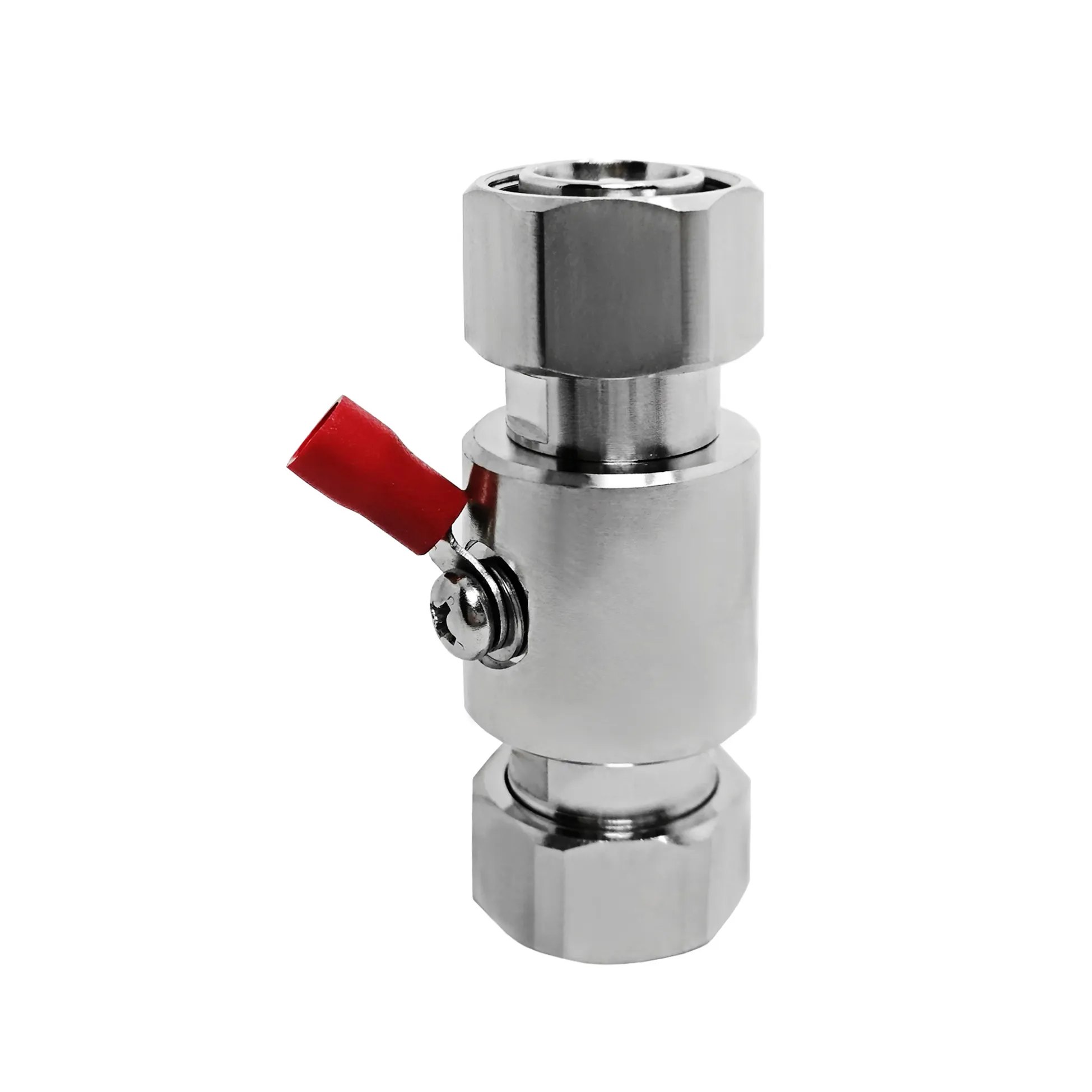
ODM development projects rarely fail because an engineering team lacks knowledge of what an SMA interface is. They fail because technical requirements that seemed obvious to one team were not made explicit, measurable, and revision-controlled for the next team. A male SMA connector is a threaded 50-ohm RF interface, but that short description is not a complete manufacturing requirement. It says nothing about the mating reference, cable termination, key dimensions, body plating, test conditions, packaging labels, or sign-off route. When these details move through sales, design, sourcing, production, and quality validation as informal messages, a small wording gap can escalate into a tooling change, a delayed build, or a custom RF cable assembly that fails to mate with panel ports.
For procurement managers and RF system designers, the goal is not simply sending more emails. It is establishing a controlled communication system that turns every custom ODM SMA connector requirement into a single, reviewable source of truth. Implementing this structural discipline protects both the plug side and the corresponding female SMA connector on an enclosure panel, PCB, or test fixture. Partnering with a specialized manufacturer like WORLDPEAK guarantees that drawing revisions, electrical specifications, and mechanical tolerances are completely aligned prior to pilot tool release.
Define Precise Interfaces Instead of Generic Part Names
Labeling a project document with a generic phrase like "SMA connector" creates immediate supply chain risks. The initial engineering packet must identify the precise interface at every signal node: specifying whether the design calls for a male SMA connector or a female SMA connector, standard or reverse-polarity (RP-SMA) geometry, straight or right-angle body profile, and cable-end, bulkhead, or PCB surface-mount style. Incorporating a written mating-pair definition prevents different team members from interpreting gender terms differently.
While international standards such as IEC 61169-15 define basic 50-ohm threaded interface dimensions, a general standard cannot replace an application-specific drawing package. An avoidable delay during RF system integration often starts when a purchase order specifies the interface family but omits explicit gender or polarity requirements. The manufactured components may individually pass quality checks, yet fail completely when mated on the assembly line.
Engineering Comparison: Male SMA Connector vs. Female SMA Connector Parameters
To ensure unambiguous communication between global design teams and factory production lines, key technical boundaries must be documented across both sides of the interface.
| Parameter | Male SMA Connector (Plug) | Female SMA Connector (Jack / Receptacle) |
| Coupling Mechanics | Internal 1/4-36 UNS Threading with Hex Coupling Nut | External 1/4-36 UNS Threading for Nut Engagement |
| Center Pin Configuration | Solid Center Pin (Standard) or Socket (RP-SMA) | Receptacle Socket (Standard) or Center Pin (RP-SMA) |
| Dielectric Alignment | Flush to Mating Plane (PTFE / High-Temp Dielectric) | Fixed Seating against Panel or Connector Housing |
| Primary Mounting Style | Direct Coaxial Cable Crimp / Solder, In-Line Adapter | Panel Bulkhead Flange, PCB Thru-Hole, Edge Launch |
| Recommended Mating Torque | 7–10 in-lbs (0.8–1.1 Nm) for Brass / Stainless Steel | 7–10 in-lbs (0.8–1.1 Nm) when mated with Male Plug |
| Typical Applications | Custom RF Cable Assembly ends, Antenna Pigtails | Radio Enclosure Panels, Base Station Modules, Test Ports |
Construct a Comprehensive Requirements Matrix Before Prototype Builds
Prevent communication errors by consolidating scattered specifications into one controlled matrix. Every technical requirement must be assigned an owner, a reference document, a revision letter, and an explicit verification method. This matrix should be reviewed jointly by the RF systems engineer, mechanical designer, quality assurance lead, and the ODM SMA connector project manager.
Core Categories for the ODM SMA Connector Matrix:
-
Electrical Targets: Nominal 50-ohm impedance, frequency bandwidth (e.g., DC to 6 GHz or DC to 18 GHz), maximum allowable Return Loss (VSWR), insertion loss budgets, and reference calibration planes.
-
Mechanical Specifications: Male SMA connector or female SMA connector classification, drawing revision number, body geometry, matching coaxial cable family, stripping dimensions, and mating-cycle expectations.
-
Material and Plating Callouts: Base material selection (machined brass vs. stainless steel), body plating (nickel vs. gold vs. tri-metal), center pin gold plating thickness, and RoHS/REACH compliance.
-
Quality Verification Protocols: Sampling plan, visual cosmetic criteria, pin depth measurements, continuity checks, and Vector Network Analyzer (VNA) test setups.
Use Controlled Drawings as the Communication Anchor
A part number is merely a line-item index; a released engineering drawing is the contractual argument. The drawing package must show the mating interface face, center-conductor pin depth, thread callouts, finished length reference points, and revision history. Annotated photos are useful for supplementary context, but they must never replace a revision-controlled CAD file or 2D PDF drawing.
For a male SMA connector, define which dimensions are critical to electrical contact and which are non-critical cosmetic boundaries. For a female SMA connector, state whether overall length is measured from the panel mounting flange, the rear solder tail, or the outer mating plane. Clarifying these baseline measurement points prevents common handoff mistakes during incoming quality control.
Before cutting tooling or building pilot batches, require a formal "read-back" from the factory. The ODM supplier returns the requirements matrix and drawing with every feature marked as understood, unclear, or requiring modification. Resolving questions in the central file avoids miscommunication later in production.
Establishing Revision Control via Decision Gates
Engineering changes occur frequently during custom ODM SMA connector development—a housing wall shifts, cable routing changes, or a new contact plating is selected. Managing changes through informal chats or email chains without updating drawing packages leads to revision drift and production errors.
Formal Change Management Workflow:
-
Proposed Engineering Change: Identify the technical reason for the modification and outline affected assembly parameters.
-
Impact Assessment: Evaluate potential effects on electrical performance, mechanical tolerance, lead times, and cost limits.
-
Update Controlled Drawings: Modify the master CAD package and requirements matrix with updated revision letters.
-
Issue Engineering Change Order (ECO): Re-validate physical samples and formally retire the prior drawing revision across all departments.
When a change is required, document the proposed modification, evaluate its effect on electrical and mechanical performance, update the master drawing package, and issue a formal Engineering Change Order (ECO). Retiring old drawing revisions at both the customer facility and the factory floor ensures that subsequent production lots use the correct specification.
Cross-Functional Sample Approval Protocol
Sample approval should never rely on visual inspection alone. The evaluation must engage the same cross-functional team responsible for system performance:
-
Electrical Verification: Measure S-parameters (VSWR and Return Loss) on a calibrated Network Analyzer across the specified operating frequency range.
-
Mechanical Fit Check: Mate the sample male SMA connector with the intended panel-mounted female SMA connector to confirm thread engagement, torque limits, and clearance.
-
Workmanship Inspection: Check ferrule crimp heights, pin concentricity, center contact gold plating, and strain-relief heat-shrink positioning on the custom RF cable assembly.
-
Documentation Review: Verify that the physical sample labels, lot numbers, and pre-shipment sweep test records match the released drawing package.
Working directly with an established RF manufacturer like WORLDPEAK provides access to complete lot-level traceability, factory-direct technical reviews, and pre-shipment test documentation. This cross-functional discipline eliminates communication errors, protects signal integrity, and guarantees smooth volume production for every ODM SMA connector program.





