 EN

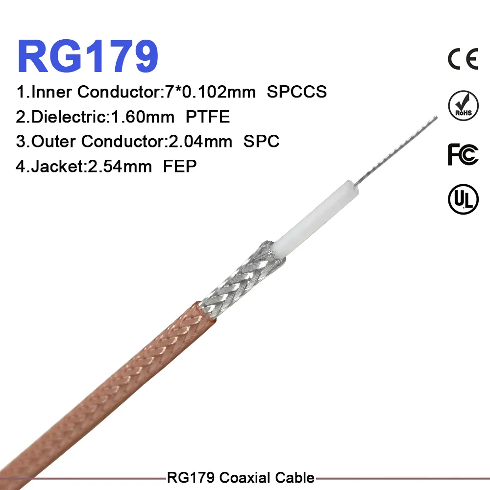
In high-reliability OEM manufacturing, an rf cable adapter is far more than a simple line item on a bill of materials. Positioned at critical transmission junctions across 5G telecom towers, industrial automation lines, and high-frequency test environments, a single sub-standard oem coaxial adapter directly dictates total system signal integrity, return loss performance, connector contact wear, and long-term field stability.
While selecting a lower-cost interconnect might seem like an easy victory for unit-price reduction, unverified mechanical tolerances or inconsistent plating from a non-certified vendor can trigger costly assembly line rework, intermittent signal drops, and massive warranty claims.
To build a resilient supply chain, engineering and procurement teams must look past distributor catalog prices. This guide outlines how to construct a total lifecycle cost model, evaluate critical performance margins, and partner with a reliable rf connector manufacturer like WORLDPEAK to achieve true value engineering without sacrificing field reliability.
TOTAL LIFECYCLE COST (TLC) BREAKDOWN
-
Purchase Price: 15%
-
Qualification & VNA: 20%
-
Assembly & Rework: 30%
-
Field Risk & Downtime: 35%
Calculating Total Lifecycle Cost (TLC) vs. Unit Piece Price
Evaluating an oem coaxial adapter solely by initial unit price exposes OEM projects to massive hidden operational costs. A comprehensive Total Lifecycle Cost framework categorizes expenditures across four major lifecycle stages:
-
UNIT PIECE PRICE (15%): Base Procurement / Catalog Cost
-
QUALIFICATION & TESTING (20%): VNA Sweeps, Mechanical Fit Checks
-
ASSEMBLY LINE & REWORK (30%): Installation Labor, Torque Control
-
FIELD SERVICE & RISK EXPOSURE (35%): Troubleshooting, System Downtime
When an unverified rf cable adapter experiences center-pin retraction or gold-plating flaking inside an active coaxial cable assembly, the cost to diagnose, access, and replace that single faulty interface during field operations can exceed its original purchase price by more than 100 times.
Defining System Functional Constraints First
To avoid paying for unnecessary laboratory-grade features—or conversely, under-specifying mission-critical transmission paths—engineering briefs must define five core technical boundary conditions before engaging an rf connector manufacturer:
CRITICAL OEM TECHNICAL BOUNDARIES
-
Operating Frequency & Bandwidth: Determines VSWR threshold and body geometry
-
Characteristic Impedance: Ensures 50-ohm or 75-ohm continuity
-
Mating Interface & Retention: Defines BNC, SMA, N-Type, or 7/16 DIN needs
-
Environmental & Mechanical Stress: Governs IP ratings, thermal, and vibration
-
RF Shielding & PIM Rating: Controls cross-talk and signal distortion
The Role of International Standards
Referencing international frameworks like the IEC 61169 series establishes an essential baseline for physical dimensions, interface grades, and electrical testing protocols. However, simply writing an IEC standard on a purchase order is rarely sufficient.
An oem coaxial adapter installed inside a climate-controlled data center cabinet operates under far milder stress than an rf cable adapter mounted on an exposed marine radar tower. In mild environments, standard commercial nickel plating delivers excellent economic value. On outdoor telecom towers, skimping on plating thickness or environmental sealing directly leads to rapid corrosion, impedance degradation, and immediate system failures.
Specification Matrix: Mandatory Gates vs. Tradeable Parameters
Dividing your project requirements into non-negotiable performance gates and tradeable parameters prevents unnecessary compromises during technical and commercial supplier reviews:
| Category | Parameter | Standard Commercial Spec | High-Reliability OEM Spec | Cost & Risk Impact |
| Mandatory Gate | Nominal Impedance | Standard 50 Ω / 75 Ω | Precision 50 Ω / 75 Ω Continuity | Critical: Mismatches cause immediate signal reflection. |
| Mandatory Gate | Frequency & VSWR | DC to 3 GHz (VSWR < 1.3) | DC to 18+ GHz (VSWR < 1.15) | High: Drives internal machining tolerances. |
| Mandatory Gate | Interface Geometry | Standard Commercial IEC 61169 | High-Precision Custom Tolerances | Critical: Ensures seamless mating with any coaxial cable assembly. |
| Tradeable | Plating Material | Flashed Gold / Nickel | 30µ" Gold Center / Tri-Metal Body | Moderate: Over-specifying gold on static internal lines burns budget. |
| Tradeable | Packaging & Cosmetics | Individual Polybags / Polished | Bulk Tray / Standard Industrial | Low: Streamlining packaging cuts volume unit cost. |
| Tradeable | Qualification Sample | 100% Factory VNA Swept Batch | Standard AQL Sampling Plan | Moderate: Balances testing labor against batch size. |
Validating Integrated Paths: Why Component-Level Testing Is Not Enough
A frequent procurement mistake is evaluating an oem coaxial adapter in isolation. In high-frequency applications, connectors, transitions, and cable bodies function together as an integrated RF transmission system. Even the highest-grade rf cable adapter will create severe signal bottlenecks if paired with improper cable stripping, poor crimp terminations, or tight bend radii in the adjacent coaxial cable assembly.
Transmission Path Continuity:
[Signal Input] ---> [Coaxial Cable Assembly] ---> [OEM Coaxial Adapter] ---> [System Output]
Working with an experienced rf connector manufacturer like WORLDPEAK allows OEM teams to order and test complete, factory-terminated coaxial cable assembly samples. This ensures reflection coefficient, insertion loss, and mechanical strain relief parameters are verified under realistic operating conditions prior to volume production.
Staged Qualification Schedule for OEM Suppliers
To mitigate technical risk without extending engineering timelines, adopt a three-stage qualification framework when onboarding a new rf connector manufacturer:
THREE-STAGE QUALIFICATION FRAMEWORK
-
STAGE 1: Mechanical & Dimensional Verification
-
Measure thread pitch, pin retention, dielectric positioning, and plating.
-
-
STAGE 2: Electrical & RF Performance Sweeps
-
Conduct VNA sweeps for VSWR, insertion loss, and return loss up to max frequency.
-
-
STAGE 3: Process Audits & Production Consistency
-
Verify material traceability, lot inspection logs, and ISO/CE compliance.
-
Leveraging Strategic Supplier Collaboration
When issuing Requests for Quotation (RFQs), provide your chosen rf connector manufacturer with complete application details: target frequency, mechanical installation constraints, environmental exposure, and estimated annual volumes.
Experienced manufacturing partners like





