 EN

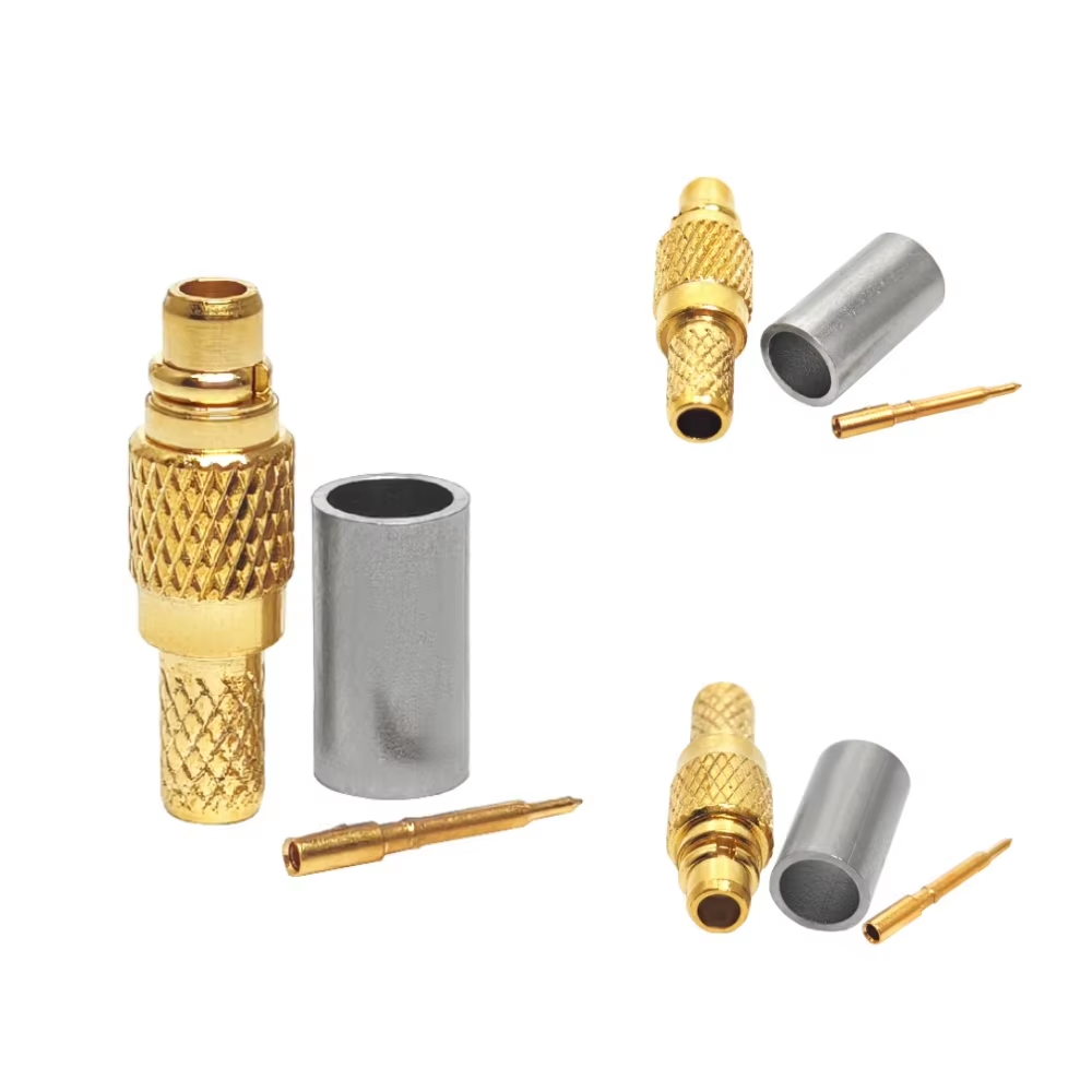
In original equipment manufacturing (OEM) projects, custom RF interconnect failures rarely occur because an engineering drawing was completely missing. More frequently, the drawing exists but leaves room for two equally plausible technical interpretations: a maximum frequency limit specified without test conditions, a plating callout missing thickness range tolerances, or an interface series name without explicit gender, keying, or pin configurations. Treating early engineering reviews with qualified rf connector suppliers as an obligatory quotation step rather than a rigorous technical confirmation gate introduces significant quality risk.
Before cutting tooling, producing prototypes, or issuing production purchase orders, engineering and procurement teams must translate application needs into a controlled technical specification package. Working closely with an experienced RF connector manufacturer ensures that mechanical interfaces mate precisely, electrical link budgets remain intact, and acceptance evidence is fully documented.
Phase 1: Define System Envelope & Signal Path Requirements
Relying solely on shorthand designations like "SMA," "N-Type," or "4.3-10" leaves key manufacturing variables unassigned. To specify a custom OEM RF connector, begin by defining the complete electrical and mechanical environment:
-
System Environment & Application Context: Specify the device type (e.g., base station transceiver, phased-array radar, medical imaging equipment, or outdoor DAS node), mounting location, expected mating cycles, operating temperature limits, and vibration exposure.
-
Electrical Path Characteristics: Define nominal system impedance (typically 50 Ohm or 75 Ohm), operating frequency bandwidth (DC to X GHz), maximum continuous and peak power handling, maximum allowable insertion loss, and target Voltage Standing Wave Ratio (VSWR) or return loss across the operating band.
-
Phase & Electrical Length Control: If your system utilizes phased array antennas or differential signaling where phase matching is critical, specify phase tolerance angles or delay times in picoseconds early in the design review.
Providing prospective rf connector suppliers with a comprehensive application statement enables engineers to flag potential mismatch issues between proposed interface designs and real-world service conditions before component tooling begins.
Phase 2: Interface Configuration & Mechanical Tolerances
Mechanical misalignment and impedance discontinuities at termination interfaces represent a major source of signal loss and passive intermodulation (PIM) issues in RF systems.
| Mechanical Parameter | Standard Commercial Spec | High-Reliability OEM Spec | Precision Test-Grade Spec |
| Interface Series & Gender | Standard Male/Female Plug | Defined Keying, RP / Standard | Precision Thread / Push-Pull |
| Center Pin Plating | Gold Flash (1–3 u in.) | Heavy Gold (30–50 u in.) over Nickel | Hard Gold (50+ u in.) over Copper |
| Body Material & Finish | Brass / Flash Nickel | Stainless Steel or Brass / Tri-Metal | Stainless Steel / Passivated |
| Dielectric Material | Standard PTFE | High-Temp / Low-PIM PTFE | Air-Dielectric / Precision PTFE |
| Coupling Mechanism | Threaded / Bayonet | Threaded with Torque Limits | Precision Threaded / Quick-Lock |
When reviewing custom designs with an RF connector manufacturer, audit critical mechanical dimensions that impact mating repeatabilities, such as thread geometry, dielectric recess depth, pin retention force, panel cutout profiles, board stack heights, and cable stripping step dimensions. For cable-mounted connector designs, supply exact cable construction cross-sections, as slight variation in dielectric diameter across cable suppliers requires adjusted crimp ferrules or solder pocket dimensions.
Phase 3: Material Selection, Plating & Environmental Specifications
Sub-tier material selection directly impacts electrical performance, corrosion resistance, and operational lifespan under severe field conditions:
-
Contact & Shell Materials: Specify beryllium copper (BeCu) or phosphor bronze for spring contacts requiring high yield strength over repeated mating cycles. Shell bodies typically utilize brass for general commercial use, or passivated stainless steel for high-corrosion aerospace environments.
-
Plating Specifications & Thickness Ranges: Avoid vague terms like "gold plated." Instead, define exact plating thickness ranges (e.g., 50 micro-inches of gold per MIL-G-45204 over 100 micro-inches of electroless nickel per AMS-QQ-N-290). For low-PIM applications, select non-magnetic tri-metal (white bronze/SUCOPLATE) or silver plating.
-
Environmental Ratings: Define measurable testing thresholds, including operating temperature range (-55°C to +125°C), salt spray corrosion resistance (e.g., 48-hour or 96-hour ASTM B117 tests), ingress protection ratings (IP67 / IP68 submerged), and shock/vibration parameters (MIL-STD-202 Method 213/204).
Phase 4: Acceptance Test Plans & Standard Industry Frameworks
A complete OEM RF connector specification must establish an enforceable acceptance test plan (ATP) that defines testing fixtures, calibration protocols, sampling sizes, and pass/fail thresholds before production release.
Leverage established industry specification standards as baseline reference frameworks:
-
IEC 61169 Series: International standards governing general requirements, dimensions, and mechanical/electrical test methods for RF coaxial connectors.
-
MIL-PRF-39012: Detailed specification standards covering general design, performance requirements, and qualification procedures for high-reliability military coaxial connectors.
When partnering with leading rf connector suppliers like
Pre-Production Technical Confirmation Checklist
Before issuing final production sign-offs to your chosen RF connector manufacturer, verify that every item on this pre-production checklist is documented and agreed upon:
-
Is the drawing revision locked, uniquely numbered, and signed off by both buyer and supplier engineering teams?
-
Are interface series, gender, polarity, coupling mechanism, and mounting styles fully defined without ambiguity?
-
Have plating types and minimum thickness ranges for shells, outer contacts, and inner pins been explicitly defined?
-
Are mechanical dimensions, PCB solder footprints, or cable preparation stripping schedules verified against mating parts?
-
Is the electrical acceptance test plan (frequency band, maximum VSWR, maximum insertion loss, and sample size) locked?
-
Are environmental compliance requirements (RoHS, REACH, IP rating, salt spray) backed by material certs and test reports?
-
Has a formal Engineering Change Order (ECO) process been agreed upon to prevent unapproved material substitutions?
By enforcing a controlled specification confirmation process prior to tooling and serial production, procurement and engineering teams eliminate costly design iterations, streamline incoming inspection, and ensure high-reliability performance across every shipped unit.





