 EN

Submitting an OEM coaxial connector development package requires clear, unambiguous engineering data to ensure rapid prototyping and reliable mass production. In high-frequency RF systems, a photograph or generic part name is never sufficient for manufacturing approval. Two interfaces may look identical visually, yet differ drastically in nominal impedance, dielectric material, pin geometry, plating thickness, or cable retention design.
From an international procurement and engineering perspective, successful OEM coaxial connector development depends on establishing complete traceability between physical prototype samples, controlled 2D/3D engineering drawings, and precise electrical test specifications. When global buyers skip these steps, prototypes may fit mechanically during initial bench trials but fail disastrously under production line testing or field exposure. Partnering with an experienced manufacturer like WORLDPEAK ensures every custom RF coaxial connector meets strict tolerance and signal integrity standards before entering volume production.
Define Application Requirements Before Requesting Samples
Before submitting a sample request for OEM coaxial connector development, clarify where the component sits within the RF signal path. RF engineers must evaluate the complete transmission channel, ensuring that the connector, interface gender, contact plating, and internal geometry match the matching coaxial cable construction.
Essential Application Inputs:
-
System Operating Frequency Range: Specify both typical operating frequencies and maximum bandwidth headroom (e.g., DC to 6 GHz, DC to 18 GHz).
-
Nominal System Impedance: Confirm 50 Ohm for RF communications and industrial equipment, or 75 Ohm for broadcast and video systems.
-
Electrical and RF Performance Limits: Define maximum permissible VSWR, insertion loss, RF shielding effectiveness, and passive intermodulation (PIM) limits.
-
Environmental and Mechanical Constraints: State IP sealing ratings, salt spray corrosion requirements, operating temperature limits, panel mounting thickness, rear enclosure clearance, and total mating cycles.
If your project is deciding between different RF coaxial connector types (such as SMA, N-Type, BNC, TNC, or 4.3-10), state clearly whether the primary decision driver is physical size, frequency capability, cable diameter fit, power handling, or existing system interface compatibility.
What to Include in the Technical Drawing Package
A fully controlled engineering drawing package forms the contractual baseline for OEM coaxial connector development. Always supply the latest PDF drawing alongside native 2D (DXF/DWG) or 3D CAD files (STEP/IGES) when available. The revision level must be clearly marked on every document, matching the RFQ, sample packaging, and technical correspondence.
The drawing must clearly classify the coaxial connector as a plug (male), jack (female), bulkhead mount, PCB mount, flange mount, or custom inline RF adapter.
Key Drawing Checklist:
-
Interface and Gender Definition: Series, gender, polarity, coupling style, and thread specification.
-
Electrical Specifications: Nominal impedance, operating frequency range, VSWR limits, and insertion loss limits.
-
Critical Mechanical Geometry: Envelope dimensions, panel cutouts, PCB pin footprint, thread pitch, and manufacturing tolerances.
-
Cable Termination Profile: Crimp, clamp, or solder specifications, cable strip dimensions, and center contact treatment.
-
Material Stack and Plating: Body material, contact substrate, plating thickness, and environmental compliance requirements.
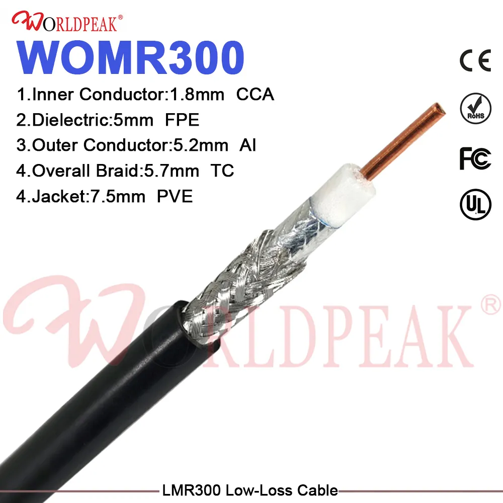
Cable outside diameter (OD) and dielectric dimensions require specific documentation. While cable OD is a primary input for matching body dimensions, complete cable cross-section data—including braid coverage, shield layer construction, and core dielectric material—is critical to designing precise crimp ferrule or solder termination features.
Guidelines for Shipping Identifiable Prototyping Samples
A complete sample submission package should contain multiple clearly marked prototype units rather than loose, unlabelled parts. Each physical sample must include a durable tracking label specifying the RFQ number, drawing revision, sample lot number, and manufacture date.
When sending custom RF cable assemblies, document the exact finished length, end-A and end-B connector configurations, strain-relief boots, heat-shrink tubing specifications, and internal soldering or crimping methods. High-resolution photos showing both assembled units and close-up termination cross-sections should supplement the drawing package.
When evaluating prototype samples for OEM coaxial connector development, ask the vendor to explicitly declare which features use final production tooling and which rely on temporary machining or manual assembly. A hand-turned brass prototype demonstrates physical dimensions, but hard tooling and automated plating lines are required to confirm high-volume repeatability.
OEM Sample Evaluation Framework
To prevent subjective acceptance, engineering teams should evaluate submitted prototypes against a structured comparison matrix before approving changes or releasing pilot production.
| Inspection Parameter | Evaluation Focus & Criteria | Measurement Method / Tool | Verification Result |
| Interface Fit & Threading | Mating engagement, keying alignment, coupling nut smooth turn, panel clearance | Mating gauge, torque wrench, physical test board | Pass / Fail & Torque (Ncm) |
| Mechanical Dimensions | Outer envelope, thread pitch, cable entry ID, PCB pin location | Optical comparator, vernier caliper, micrometers | Recorded dimensions vs. drawing tolerances |
| RF Electrical Behavior | Target frequency range, return loss (VSWR), insertion loss | Vector Network Analyzer (VNA) calibrated to test band | S11 / S21 Smith Chart plots |
| Assembly & Termination | Crimp hex retention, solder wetting, heat-shrink positioning, contact retention | Cable pull-force tester, cross-section microscope | Pull-force value (N) & Visual photo |
| Material & Plating Quality | Body plating thickness, center contact gold coverage, salt spray resistance | X-ray fluorescence (XRF) gauge, salt spray chamber | Micron thickness readout |
| Revision Control | Sample physical marking vs. BOM revision vs. CAD file revision | Document cross-check | Verified matching revision |
Selecting RF Coaxial Connector Types via Decision Path
Choosing the correct interface for custom RF cable assemblies or equipment enclosures requires a systematic decision workflow. Visual appearance can be deceiving; relying on photos rather than dimensioned engineering drawings frequently leads to electrical mismatch or mechanical damage during mating.
Decision Workflow Steps:
-
Check Existing Mating Interface: Determine whether the interface is fixed by legacy equipment or completely open for new design selection.
-
Establish Target Frequency and Power: Match high-frequency requirements with smaller precision interfaces or high-power needs with larger threaded interfaces.
-
Confirm System Impedance: Ensure 50 Ohm or 75 Ohm matching across all transmission path components.
-
Select Cable Family Match: Match the connector rear entry size to the flexible, semi-rigid, or corrugated coaxial cable specifications.
-
Define Termination Method: Determine whether crimp, clamp, solder, or PCB surface-mount processing is required for assembly line balance.
For new custom designs, keep initial sample requests focused on one baseline drawing configuration. If multiple options are needed, clearly define the exact variable parameter—such as straight versus right-angle orientation, rear bulkhead flange thickness, gold vs. nickel contact plating, or crimp ferrule diameter.
Establishing Revision Control Before Pilot Production
Once physical samples pass full mechanical and electrical validation, issue a formal Sample Approval Notification (SAN). This approval record locks the baseline drawing revision, BOM specs, cable assembly drawings, and quality control acceptance criteria.
Any subsequent design changes during OEM coaxial connector development must be classified before shipment:
-
Form Changes: Alterations to housing geometry, mounting threads, or panel cutouts (requires fit re-verification).
-
Material / Plating Changes: Modifications to body metals, contact substrates, or plating thickness (requires corrosion and contact resistance re-verification).
-
Termination / Cable Changes: Changes to crimp die dimensions, solder processes, or coaxial cable brands (requires RF performance re-verification).
Working with an established manufacturer like WORLDPEAK ensures transparent revision control, rigorous pre-shipment electrical testing, and full lot-level traceability from sample submission through volume manufacturing.





