 EN

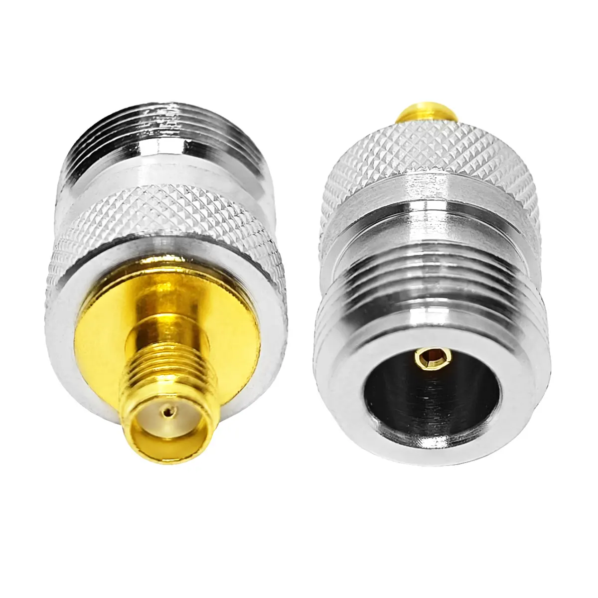
Ensuring seamless signal transmission in modern telecommunications, broadcast, and industrial RF systems relies heavily on hardware precision. When upgrading infrastructure or integrating legacy lines, correctly installing coax cord adapter units is critical. Improper mechanical assembly or poor electrical contact can lead to high Voltage Standing Wave Ratio (VSWR), signal attenuation, and costly downtime. As a leading manufacturer at
Essential Tooling and Pre-Installation Inspection
Before initiating the physical assembly of a coax cord adapter, gathering professional-grade tools ensures mechanical integrity and prevents microscopic damage to delicate dielectrics and center conductors.
-
Coaxial Cable Stripper: Calibrated for precise jacket, braid, and dielectric cutting lengths.
-
Calibrated Crimp Tool or Torque Wrench: Essential for maintaining consistent clamping force without crushing the cable shield.
-
Lint-Free Isopropyl Alcohol Wipes: Used to clean microscopic metallic residue or oxidation from contact surfaces.
-
Visual Magnifier / Inspection Scope: For verifying center pin seating and dielectric cleanliness.
When unpacking your coax cord adapter, inspect the inner contact pin, outer housing threads, and sealing gaskets. Factory-certified components from Worldpeak undergo stringent optical and electrical quality checks to guarantee low insertion loss across microwave and VHF/UHF frequency spectrums.
Step-by-Step Procedure for Installing Coax Cord Adapter
Executing the installation with mechanical precision ensures optimal impedance matching (typically 50 Ohms or 75 Ohms depending on the system requirement). Follow these four core engineering steps:
Step 1: Precision Cable Preparation and Stripping
Measure the coaxial cable end according to the specific manufacturer datasheet for your chosen coax cord adapter. Insert the cable into the rotary coaxial stripper. Rotate the tool evenly to score the outer PVC or PE jacket, the braided copper or aluminum shield, and the inner dielectric foam or PTFE layer without nicking the center conductor. Expose the center conductor to the exact length specified for pin insertion.
Step 2: Braid Flaring and Shield Preparation
Carefully comb out or fold back the outer braided shield and foil layer over the outer cable jacket. Ensure that no stray wire strands remain loose, as stray copper filaments can cause micro-shorts against the center pin or inner housing of the coax cord adapter, destroying signal fidelity.
Step 3: Inserting and Securing the Center Conductor
Gently slide the center pin or contact over the exposed center conductor of the cable. Depending on whether you are installing coax cord adapter units featuring crimp, clamp, or solder terminations, apply the appropriate fastening method:
-
Crimp Style: Position the specified crimp die over the pin and compress firmly until the ratchet releases.
-
Clamp Style: Ensure the internal gasket, washer, and clamp nut compress the braid evenly against the adapter body.
-
Solder Style: Apply controlled heat with a precision iron, using minimal solder to prevent pooling that could alter characteristic impedance.
Step 4: Final Housing Assembly and Torque Control
Thread or push the main body of the coax cord adapter onto the prepared cable assembly until fully seated. Tighten the coupling nut or threaded housing to the recommended torque specification using a calibrated torque wrench. Over-tightening can deform internal dielectric insulators, while under-tightening can introduce moisture ingress and loose ground contact, leading to intermittent signal dropouts.
Comparative Analysis of Installation Methods
Different deployment environments require specific fastening techniques for coaxial adapter installation. The table below compares common methods utilized in industrial and telecommunication projects.
| Installation Method | Mechanical Stability | Environmental Sealing | Best Application Scenario | Typical VSWR Performance |
| Crimp-Type | High (Permanent grip) | Moderate (Requires heat shrink) | Indoor telecom racks, high-density patch panels | Excellent ($< 1.15$ up to 3 GHz) |
| Clamp-Type | Superior (Reusable) | High (Integrated O-rings) | Outdoor antenna towers, broadcast transmission lines | Very Good ($< 1.20$ up to 6 GHz) |
| Solder-Type | Moderate (Vibration sensitive) | Low (Requires sealant) | Laboratory test benches, legacy instrumentation | Standard ($< 1.25$ up to 2 GHz) |
Common Pitfalls and Troubleshooting During Installation
Even experienced technicians can encounter performance bottlenecks during installing coax cord adapter tasks. Avoiding these frequent mistakes ensures long-term system reliability:
-
Dielectric Melt or Deformation: Applying excessive heat during soldering can warp the PTFE or foam dielectric, shifting the impedance and causing signal reflections.
-
Contaminated Contact Surfaces: Dust, oils from skin, or metallic shavings inside the connector interface increase contact resistance. Always clean mating surfaces with pure alcohol before final mating.
-
Mismatched Impedance Interfaces: Mixing 50 Ohm and 75 Ohm hardware creates abrupt impedance discontinuities, resulting in high return loss and degraded system performance. Verify that your coax cord adapter matches the characteristic impedance of both your feedline and connected equipment.
Conclusion and Quality Assurance
Mastering the art of installing coax cord adapter components safeguards your entire RF network against attenuation, reflection, and environmental degradation. By adhering to strict mechanical preparation standards and utilizing precision-engineered hardware from trusted partners like Worldpeak, you guarantee robust, high-frequency performance across mission-critical deployments. For further technical specifications or custom connector solutions, explore our comprehensive range of high-reliability interconnect products on the





