 EN

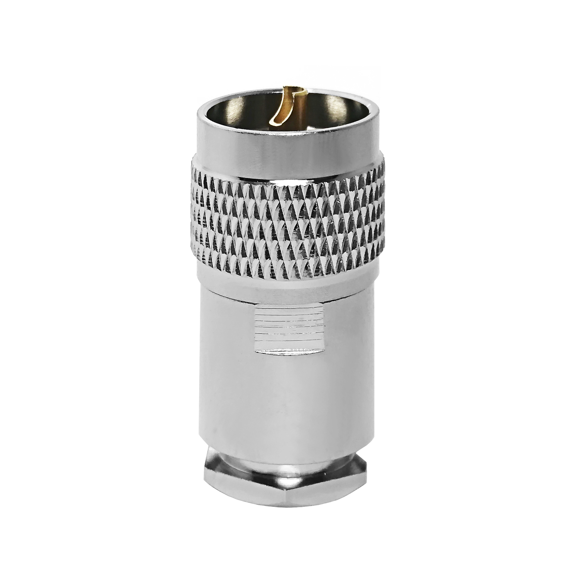
When deploying mobile radio communications, vehicular antenna arrays, and space-constrained two-way radio setups, achieving a reliable and mechanically secure RF termination is paramount. Among various compact RF interconnects, the mini UHF connector is widely specified due to its threaded coupling mechanism, miniature footprint, and stable impedance performance up to 2.5 GHz. However, because of its compact scale, improper cable preparation or sloppy soldering can easily lead to high voltage standing wave ratio (VSWR) spikes, intermittent contact, and signal attenuation. Worldpeak RF Connectors has established rigorous engineering guidelines for correctly installing mini UHF connector assemblies onto standard low-loss coaxial cables. This practical guide walks field technicians and assembly engineers through professional termination protocols, ensuring flawless mechanical integrity and optimal high-frequency electrical performance.
Phase-by-Phase Termination Protocol for Field Technicians
Executing a precision coaxial cable assembly requires exact strip lengths, clean conductor trimming, and meticulous solder or crimp management. When installing mini UHF connector hardware onto cables such as RG-58 or similar flexible RF lines, technicians must adhere to a strict chronological sequence to prevent dielectric distortion and shield fraying.
Step 1: Precision Cable Preparation and Jacket Stripping
Begin by sliding the knurled outer shell and any applicable strain-relief boots onto the coaxial cable before starting any stripping. Using a calibrated rotary coaxial cable stripper, score the outer protective PVC jacket at the exact manufacturer-specified dimension. Peel away the outer jacket to expose a clean section of the metallic braided shield without nicking or scoring the individual strands.
Step 2: Shield and Dielectric Trimming
Comb out the exposed braided shield smoothly over the outer jacket or trim it back evenly depending on the specific clamp or crimp style of the mini UHF connector. Next, measure and strip the inner polyethylene dielectric core to expose the solid or stranded center conductor. Take extreme care not to scratch or weaken the center conductor during insulation removal, as surface imperfections can trigger micro-arcing and signal reflection at higher operational frequencies.
Step 3: Conductor Tinning and Center Pin Attachment
If utilizing a solder-type mini UHF connector, lightly tin the exposed center conductor with a controlled-temperature soldering iron using high-purity rosin-core solder. Insert the center conductor into the connector pin or socket terminal, applying heat uniformly until the solder flows evenly into the barrel. Avoid excess solder buildup that could alter the inner diameter or prevent smooth mating with corresponding equipment ports.
Step 4: Housing Assembly and Threaded Engagement
Carefully slide the main body of the mini UHF connector over the prepared dielectric and center pin sub-assembly. Ensure that the internal grounding fingers or clamp sleeves make 360-degree continuous contact with the braided shield. Finally, thread and torque the outer coupling barrel securely to the specified factory rating, verifying that no rotational strain is placed on the internal center pin during final tightening.
Common Installation Pitfalls and Prevention Matrix
Even experienced technicians occasionally encounter termination errors when installing mini UHF connector components in high-pressure field environments. The troubleshooting matrix below outlines common assembly mistakes, their electrical consequences, and professional prevention methods.
| Installation Mistake | Electrical Consequence | Field Symptom | Professional Prevention Method |
| Nicking the Center Conductor | Reduced mechanical strength and localized impedance bump | Intermittent signal loss under vibration | Use calibrated rotary strippers with adjustable blade depths |
| Excess Solder on Center Pin | Impedance mismatch and capacitive discontinuity | Elevated VSWR across the 2 GHz band | Use temperature-controlled irons and measured solder volume |
| Stray Braid Strands Touching Pin | Direct short circuit between signal and ground | Complete transmitter failure or zero power output | Trim stray braid whiskers thoroughly before housing insertion |
| Under-Torqued Coupling Barrel | Loose mechanical contact and increased insertion loss | Signal fluttering when cable is moved | Torque threaded barrels using calibrated service wrenches |
Quality Assurance and Inspection Standards at Worldpeak
EEAT compliance requires transparent manufacturing and rigorous quality control protocols. At Worldpeak RF Connectors, every production batch and custom coaxial cable assembly undergoes stringent multi-stage inspection to guarantee field reliability. Following the termination of any mini UHF connector, assemblies are subjected to 100% automated vector network analyzer (VNA) sweep testing. Technicians verify that return loss exceeds 26 dB and that insertion loss remains below 0.2 dB across the operating bandwidth. Furthermore, pull-test mechanical validation ensures that the terminated mini UHF connector can withstand heavy tensile loads without shield slippage or center pin pull-out, meeting strict ISO 9001 quality management benchmarks.
Conclusion and Best Practices for Reliable Deployment
Mastering the art of installing mini UHF connector hardware ensures long-term operational stability, eliminates costly maintenance callbacks, and protects sensitive transceiver equipment from high-VSWR reflection damage. By following strict stripping measurements, maintaining clean solder joints, and performing post-assembly VNA testing, engineering teams can achieve pristine RF signal transmission in mobile and compact communication environments.
For a comprehensive overview of system architecture, multi-frequency design principles, and full product catalogs, explore our primary pillar guide on





