 EN

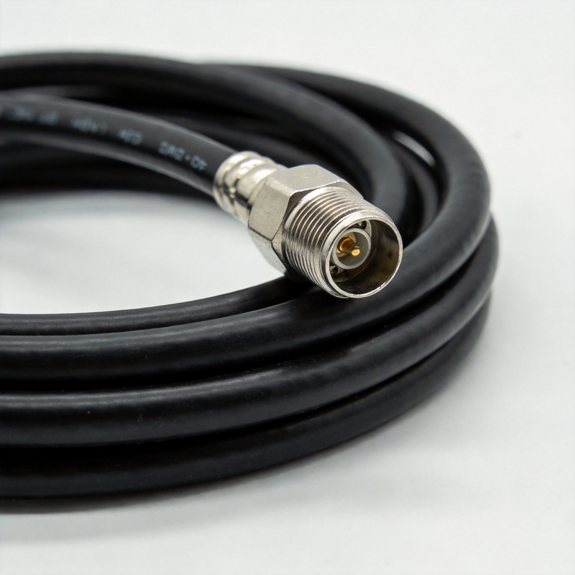
Low-Loss RF Cables: LMR and Foam-Dielectric Types
For an RF system buyer, an rf low loss cable is not simply a coaxial cable with a favorable attenuation figure. It is a transmission-line choice that has to survive the route, preserve the intended impedance, accept the selected connector family, and remain practical for installation teams. That is why an LMR-style cable and another foam-dielectric coax of a similar diameter can be alternatives without being interchangeable.
In connector and cable-assembly discussions, the useful starting point is the whole link: frequency range, run length, source and load impedance, bend locations, outdoor exposure, and the interfaces at both ends. The following comparison is designed for telecom, industrial, security, laboratory, and infrastructure procurement teams that need to turn those requirements into a repeatable specification.
What makes an rf low loss cable low loss?
Coax attenuation comes from conductor and dielectric losses, and both become more consequential as operating frequency rises. Larger conductors generally reduce resistive loss, while a lower-effective-permittivity dielectric can help reduce dielectric loss. This explains why a larger rf low loss cable often has lower published loss per unit length than a smaller cable in the same family. It also explains why the comparison must be made at the same frequency, temperature basis, and length unit.
Foam dielectric uses gas cells within the insulating material to reduce its effective dielectric constant. The design can support attractive attenuation and velocity characteristics, but the cable still depends on controlled geometry and an intact jacket. If water reaches a construction not intended for the environment, long-term electrical stability can suffer. Low loss is therefore a system property, not a label to copy from a catalog line.
LMR-style versus foam-dielectric coax: the practical difference
LMR-style is commonly used as a shorthand for flexible 50-ohm low-loss coax constructions. Many versions combine a stranded center conductor, foam dielectric, foil, braid, and protective jacket. “Foam-dielectric cable” is the broader construction category: it can include flexible jumper cable, heavier feeder, semi-flexible corrugated designs, and different shielding layouts. Ask the supplier for the actual construction and data sheet rather than treating either name as a universal standard.
| Selection factor | LMR-style flexible coax | Other foam-dielectric low-loss types |
|---|---|---|
| Attenuation | Often a strong balance for equipment runs and antenna feeders; compare at the operating frequency. | Can range from flexible to very low-loss feeder; larger or corrugated options may favor long runs. |
| Flexibility | Usually suited to routing around cabinets, towers, and service loops within the stated bend limit. | Varies widely; larger feeder and corrugated constructions need more route planning. |
| Shielding | Foil-and-braid designs can provide useful coverage while retaining flexibility. | May use braid, foil, multiple layers, or a corrugated outer conductor depending on purpose. |
| Connectorization | Commonly field-terminated or factory assembled with compatible 50-ohm RF interfaces. | May require cable-specific preparation tools and connector families. |
Attenuation: compare the complete operating condition
Procurement should request attenuation at the intended frequency, not a single low-frequency headline value. A cable that is acceptable for a short 400 MHz jumper may impose a different budget at multi-gigahertz frequencies or over a long rooftop run. Add connector and adaptor insertion loss, the number of interfaces, and a sensible installation margin to the link budget.
Diameter is the usual first trade-off. A larger rf low loss cable can lower loss per meter, but it weighs more, needs a larger bend radius, and can increase hardware and routing effort. A smaller flexible cable may be the sensible choice inside a cabinet where service access matters more than saving a fraction of a decibel. For outdoor feeders, calculate total run loss first, then verify that the chosen cable can be installed without forced bends.
Flexibility, shielding, and mechanical routing
A flexible cable is not an invitation to exceed its minimum bend radius. Over-bending can deform the dielectric or shield, affecting impedance consistency and return loss. Specify static and repeated-flex requirements separately. A cable that is appropriate for one-time routing may not be appropriate next to a moving antenna, test fixture, or hinged enclosure.
Shield selection follows the noise environment. Foil provides broad coverage; braid contributes mechanical flexibility and low-frequency shielding performance; multi-layer approaches can balance both. Do not select only by the phrase “double shield.” Review shielding construction, jacket type, grounding practice, and nearby interference sources. For exposed or high-interference sites, the assembly layout and connector termination quality can be as important as the cable construction.
Impedance and connectorization: protect the 50-ohm path
Most RF transmit, receive, and test paths use 50 ohms, but the project specification must confirm this rather than assume it. Characteristic impedance depends on conductor geometry and dielectric properties. Mixing a 50-ohm system with a cable or interface chosen for another impedance can create reflections and reduce usable margin. Specify impedance, VSWR or return-loss requirements, and test frequency for the finished assembly.
Connector choice should be driven by frequency, power, mating cycles, environmental sealing, mounting space, and the cable’s outer diameter. Factory-built assemblies reduce variability where repeatability is important. If field termination is required, qualify the installer, stripping dimensions, torque practice, and inspection method. LMR400 Low-Loss 50 Ohm Coaxial Cable is an example of a confirmed 50-ohm product listing to review alongside its current data sheet and connector compatibility before purchase.
Deployment environment changes the answer
Indoor racks favor manageable bend radius, flame and jacket requirements, and clean connector access. Outdoor antenna runs add UV exposure, water ingress control, grounding, wind movement, and entry sealing. Industrial sites may add oils, vibration, abrasion, or electromagnetic noise. In a lab, repeatable phase behavior and gentle handling can outweigh route length. Put these conditions in the RF cable request for quotation; otherwise bidders may quote different constructions under the same generic description.
Related components deserve the same discipline. RF adaptors add interfaces, so check gender, interface series, frequency rating, and torque procedures. An RF bias tee is selected for its DC and RF path ratings as well as its connector interfaces; it does not remove the need to calculate cable loss. RF resistors used as terminations or loads should match the system impedance and applicable power conditions. Treat each item as part of one controlled RF path.
B2B selection checklist
- State system impedance, operating band, maximum frequency, power, and required return-loss or VSWR targets.
- Calculate end-to-end loss using the route length and attenuation at the actual operating frequency.
- Choose a diameter and construction that meet the loss budget without violating route, weight, or bend-radius limits.
- Define the environment: indoor, outdoor, UV, moisture, vibration, chemical exposure, grounding, and sealing needs.
- Specify shielding construction and cable-jacket requirements rather than relying on a generic low-loss description.
- List both connector ends, interface gender, adapter needs, assembly length tolerance, and whether factory assembly is required.
- Request current data sheets, lot traceability where needed, and acceptance tests for the finished cable assembly.
Component integration checks for procurement
Document the RF bias tee position before cable cutting. Confirm the RF bias tee connector interface, DC path, and RF band. Place the RF bias tee where technicians can inspect it. A second RF bias tee is not a substitute for a reviewed power plan.
Specify RF adaptors by interface, gender, and frequency range. Count every pair of RF adaptors in the loss budget. Keep approved RF adaptors with the assembly documentation. Unplanned RF adaptors create avoidable interfaces.
For test and termination points, record the impedance and power condition for RF resistors. Purchase RF resistors with the applicable connector or mounting format. Verify RF resistors during acceptance testing. Keep replacement RF resistors under the same controlled specification.
Frequently Asked Questions
Is every foam-dielectric cable an rf low loss cable?
No. Foam dielectric can support lower loss, but final attenuation also depends on diameter, conductor design, shield construction, frequency, and cable condition. Compare published values under the same test conditions.
When should a buyer choose a larger cable?
Choose a larger option when the calculated run loss threatens the link budget and the route can accommodate the added diameter, weight, and bend radius. It is a trade-off, not an automatic upgrade.
Can I select connectors after specifying the cable?
Connector selection should happen at the same time. The connector must fit the cable construction and support the required impedance, frequency, environment, and installation process.
Conclusion
The appropriate rf low loss cable is the one whose published electrical data, mechanical limits, shielding, connector system, and environmental capability match the installed link. Compare LMR-style and foam-dielectric options on the same conditions, document the full assembly, and let the measured loss budget guide the purchasing decision.





