 EN

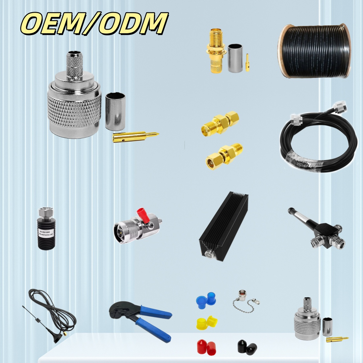
In modern telecommunications infrastructure, base stations, rooftop cell sites, and distributed antenna systems (DAS) rely heavily on a robust RF path to maintain signal integrity and ensure operational uptime. Within these high-frequency network architectures, a microwave feeder cable serves as the critical transmission highway connecting radio transceivers, power amplifiers, surge arrestors, and primary antennas. Selecting the appropriate microwave feeder cable is a complex engineering task that requires balancing RF attenuation, system link budgets, shielding effectiveness, mechanical installation constraints, and environmental durability. Deploying optimized high-frequency microwave cables ensures maximum effective radiated power (ERP) on transmit paths while keeping noise figures low on return paths.
Why Feeder Cable Performance Governs RF Link Budgets
Every microwave feeder cable deployed in an RF system introduces insertion loss, which accumulates across the entire route. This loss scales non-linearly with operating frequency, transmission distance, and conductor cross-sectional geometry. At higher microwave frequencies, even minor imperfections in dielectric consistency or outer conductor construction can lead to signal degradation, reduced cell edge coverage, and higher bit error rates. By specifying low-loss microwave cables, RF engineers preserve valuable power output from active amplifiers, preventing signal dissipation as unwanted heat energy.
In congested rooftop sites and dense macro-cellular installations, shielding effectiveness is just as important as signal loss. Premium 50-ohm corrugated copper microwave cables utilize continuous solid or annular outer conductors, providing high shielding performance, typically exceeding 120 dB. This solid metallic outer barrier prevents co-channel interference and protects signal lines from external electromagnetic interference (EMI). Furthermore, a well-shielded microwave feeder cable reduces radio frequency leakage, helping operators meet regulatory compliance standards and prevent self-interference across multi-band tower setups.
When evaluating a microwave feeder cable deployment, passive RF components along the signal path must also be accounted for. Integrating a circulator microwave device provides non-reciprocal signal routing, allowing simultaneous transmission and reception on a shared antenna path while isolating delicate transmitter equipment. Similarly, installing a ferrite isolator in microwave equipment chains absorbs reflected power generated by impedance mismatches down the line, safeguarding sensitive power amplifiers from thermal stress or permanent burnout. To maintain low loss across the entire system, both the inline circulator microwave unit and the protective isolator in microwave module must feature return loss characteristics that match the primary microwave feeder cable network.
Sizing Microwave Cables: Conductor Diameter & Trade-offs
Choosing the ideal diameter for a microwave feeder cable involves a direct trade-off between electrical performance and physical installation limits. Larger conductor diameters offer lower RF attenuation and higher continuous power capacity, but they also increase total weight, cable bend radiuses, wind load on towers, and overall structural support requirements.
| Feeder Cable Specification | 1/2 in. Superflexible | 7/8 in. Corrugated Feeder | 1-5/8 in. Corrugated Feeder |
| Typical Attenuation (GHz) | ~11.5 dB / 100m @ 2 GHz | ~6.2 dB / 100m @ 2 GHz | ~3.8 dB / 100m @ 2 GHz |
| Minimum Bend Radius | 32 mm (Single) | 125 mm (Single) | 200 mm (Single) |
| Peak Power Rating | ~15 kW | ~40 kW | ~90 kW |
| Primary Deployment | Equipment Jumpers, DAS | Macro Towers, Rooftops | Long Distance, High Power |
A 7/8 in. microwave feeder cable remains the industry standard for general macro base-station runs, striking a clean balance between manageable bending, structural weight, and low attenuation. For high-power long-distance runs where attenuation dominates the link budget, a 1-5/8 in. microwave feeder cable provides lower insertion loss, provided the tower structure can safely handle its bulk and wind exposure. Conversely, highly flexible 1/2 in. microwave cables are best suited as short equipment jumpers, bridging connections between larger feeder runs, lightning surge protectors, and antenna ports in tight spaces.
Comprehensive Procurement Specification Framework
To specify a microwave feeder cable for new network builds or site upgrades, procurement teams must supply manufacturers with precise operating parameters rather than generic descriptions like "50-ohm cable." Standardizing your technical requirements prevents unexpected site delays and rework.
-
Electrical Standards: Clearly outline the operating frequency range, nominal impedance (50 Ohm), maximum continuous average power, peak power limits, target VSWR or return loss (> 23 dB / < 1.15), and passive intermodulation (PIM) limits (e.g., ≤ -160 dBc under dynamic conditions).
-
Mechanical & Structural Limits: Define the maximum allowable outer diameter, cable weight per meter, minimum dynamic and static bend radiuses, vertical clamp spacing intervals, tray fill capacities, and flame-retardancy ratings (such as IEC 60332 or UL 1666) for indoor equipment room sections.
-
Interface & Connector Configurations: Specify precise connector interfaces (such as DIN 7/16, 4.3-10, or N-Type) fitted with silver-plated inner contacts, solid grounding mechanisms, and integrated IP68 weatherproofing systems to withstand harsh environmental conditions.
-
Passive Device Alignment: Verify that all inline passive devices—including any inline circulator microwave module or defensive isolator in microwave equipment—are specified with power ratings, frequency bandwidths, and return loss parameters that fully align with the main microwave feeder cable assembly.
For specialized deployment topologies,
Field Installation Best Practices & Site Maintenance
Even the highest-grade microwave feeder cable will suffer performance degradation if handling and weatherproofing standards are neglected during field installation. RF installers should follow established site practices:
-
Hoisting & Handling: Always adhere strictly to the manufacturer's maximum tensile load limits and minimum bend radius thresholds during tower hoisting operations. Avoid dragging microwave cables across sharp cable trays, concrete edges, or structural steel, which can deform the corrugated outer conductor and induce micro-reflections.
-
Interface Tightening & Torque Control: When connecting a microwave feeder cable to an inline circulator microwave port or protective isolator in microwave assembly, always use calibrated torque wrenches. Over-tightening can strip precision threads or crush connector pins, while under-tightening leaves gaps that introduce PIM and high VSWR spikes.
-
Weatherproofing & Sealing: Encase every outdoor junction—including main feeder runs, jumper adapters, and surge arrestor interfaces—with multi-layered weatherproofing systems, such as cold-shrink tubing or butyl rubber wrapping. Ensure seals are molded to shed water downward and carry out follow-up visual checks after the site experiences its first seasonal rain or extreme freeze-thaw cycle.
-
Commissioning & Maintenance Records: Perform rigorous site acceptance testing, including Distance-to-Fault (DTF), Return Loss, and PIM sweeps across all installed microwave cables. Retain these baseline sweep records in the site asset file, enabling maintenance technicians to quickly pinpoint physical cable damage, water ingress, or loose connector hardware during future service audits.
By standardizing every step—from calculating link budgets and sizing the microwave feeder cable, to integrating matching circulator microwave and isolator in microwave components, through to final weatherproofing and acceptance sweeps—operators build resilient RF links that maintain signal performance over years of operation.





