 EN

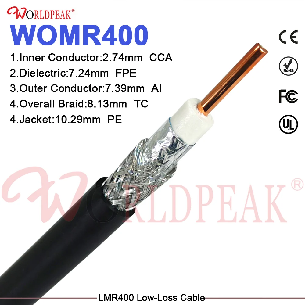
As next-generation telecommunications, automotive advanced driver assistance systems (ADAS) radar, satellite constellations, and high-speed defense electronics push operational frequencies well into the millimeter-wave spectrum, standard microwave cables experience severe performance degradation. Frequencies exceeding 40 GHz introduce intense attenuation, high insertion loss, and severe phase instability when transmitted through conventional cabling. To conquer these high-frequency bottlenecks, modern engineering teams rely on a specialized mmWave RF cable. An advanced mmWave RF cable provides the ultra-low attenuation and superior phase stability required for precise data capture and signal propagation in the 40 GHz to 110 GHz range. Worldpeak RF Connectors has engineered high-performance mmWave RF cable assemblies designed to meet the rigorous demands of millimeter-wave test benches, aerospace telemetry arrays, and 5G/6G communication infrastructure.
Overcoming High-Frequency Dielectric and Skin-Effect Losses
Operating in the millimeter-wave spectrum fundamentally changes the physical rules of electrical signal transmission. At frequencies above 40 GHz, electromagnetic energy travels almost entirely along the microscopic outer skin of the conductor due to the extreme skin effect. Consequently, surface roughness, micro-imperfections in copper plating, and molecular polarization within standard solid plastic dieletrics can ruin signal integrity.
A high-quality mmWave RF cable overcomes these physical limitations through the meticulous utilization of ultra-pure oxygen-free silver-plated copper conductors combined with low-density expanded PTFE (ePTFE) or microporous dielectric structures. Because expanded PTFE features a dielectric constant very close to that of free space, a premium mmWave RF cable dramatically minimizes phase velocity variations and dielectric absorption losses. Furthermore, precision outer conductor shielding prevents high-frequency radiation leakage, ensuring that every mmWave RF cable delivers pristine signal amplitude and ultra-low insertion loss across demanding millimeter-wave frequency bands.
Comparative Material Performance in High-Frequency Transmission
To assist design engineers in evaluating transmission media for millimeter-wave projects, the evaluation matrix below details how different dielectric and conductor materials impact high-frequency performance parameters.
| Material Configuration | Insertion Loss at 50 GHz | Phase Stability vs. Temperature | Flexibility and Bend Radius | Primary High-Frequency Deployment |
| Microporous ePTFE mmWave RF Cable | Exceptionally Low | Outstanding (Minimal drift) | High flexibility for test routing | Lab test benches, VNA patch cords, 50 GHz probing |
| Solid PTFE Coaxial Cable | Moderate to High | Moderate drift under heat | Moderate stiffness | Lower frequency microwave links, base stations |
| Solid Polyethylene Coaxial Cable | Unusable above 30 GHz | Poor (Severe thermal distortion) | High flexibility | Consumer video, legacy RF, sub-6 GHz links |
| Semi-Rigid Copper Tube Cable | Extremely Low | Superior stability | Formable once (Fixed shape) | Aerospace transceivers, satellite payload interconnects |
Real-World Engineering Deployment: 5G OTA Chamber Testing
To illustrate the critical role of a specialized mmWave RF cable in real-world scenarios, consider a recent deployment by Worldpeak for an accredited wireless certification laboratory conducting Over-The-Air (OTA) antenna testing for 5G New Radio (NR) FR2 bands operating from 24 GHz up to 52 GHz.
The testing laboratory previously encountered intermittent test failures and high measurement uncertainty caused by phase shifts and amplitude attenuation when standard test cables were flexed inside the shielded anechoic chamber. By upgrading their test harness to Worldpeak's precision-engineered mmWave RF cable assemblies featuring armored stainless steel over-braids and phase-stable ePTFE dielectrics, the laboratory resolved their testing discrepancies.
The integration of this specialized mmWave RF cable achieved a 40% reduction in insertion loss variation during robotic positioning sweeps and maintained exceptional phase stability within plus-or-minus 2 degrees across temperature fluctuations. This upgrade eliminated recalibration downtime and ensured repeatable, highly accurate test results for millimeter-wave transceiver modules.
Manufacturing Precision, VNA Sweep Testing, and Quality Control
Producing a reliable mmWave RF cable requires extreme manufacturing precision that leaves zero room for error. At Worldpeak RF Connectors, every mmWave RF cable is manufactured under rigorous ISO 9001 certified quality management protocols and adheres to international IEC and MIL-SPEC standards.
The production process follows a strict sequence:
-
Conductor Drawing and Inspection: High-conductivity copper wire undergoes laser micrometer measurement to ensure absolute uniformity before silver electroplating.
-
Dielectric Extrusion: Advanced ePTFE tape wrapping and thermal sintering machines apply the low-density dielectric core under strictly controlled tension and temperature.
-
Shielding Application: Multi-layer composite shields, including silver-plated flat wire braids and outer spiral foils, are applied to achieve shielding effectiveness exceeding 110 dB.
-
Automated VNA Sweep Testing: Every finished mmWave RF cable assembly is 100% tested using vector network analyzers operating up to 67 GHz, verifying that return loss, insertion loss, and phase tracking meet strict factory thresholds before packaging.
Strategic Considerations for Selecting High-Frequency Cabling
When procuring a mmWave RF cable for high-frequency architecture, engineering teams must carefully analyze several operational parameters:
-
Cutoff Frequency Limits: Verify that the inner and outer conductor diameters of the selected mmWave RF cable prevent higher-order mode propagation across your maximum operational bandwidth.
-
Phase and Amplitude Stability: Select cables equipped with phase-compensated dielectric materials if the assembly will experience mechanical flexing or temperature swings during operation.
-
Connector Interface Quality: Ensure that high-frequency connectors (such as 2.92 mm, 2.4 mm, or 1.85 mm precision interfaces) on the mmWave RF cable maintain precise mechanical alignment to prevent reflection spikes at mating planes.
Conclusion and Next Steps
In summary, successful deployment of systems operating above 40 GHz requires uncompromising attention to transmission line physics, material science, and manufacturing quality control. Integrating a professionally engineered mmWave RF cable safeguards high-frequency signal integrity, eliminates excessive insertion loss, and guarantees reliable performance across advanced telecommunications and aerospace applications.
To explore our comprehensive industry frameworks, multi-frequency system architectures, and complete product lineups, review our primary pillar guide on





