 EN

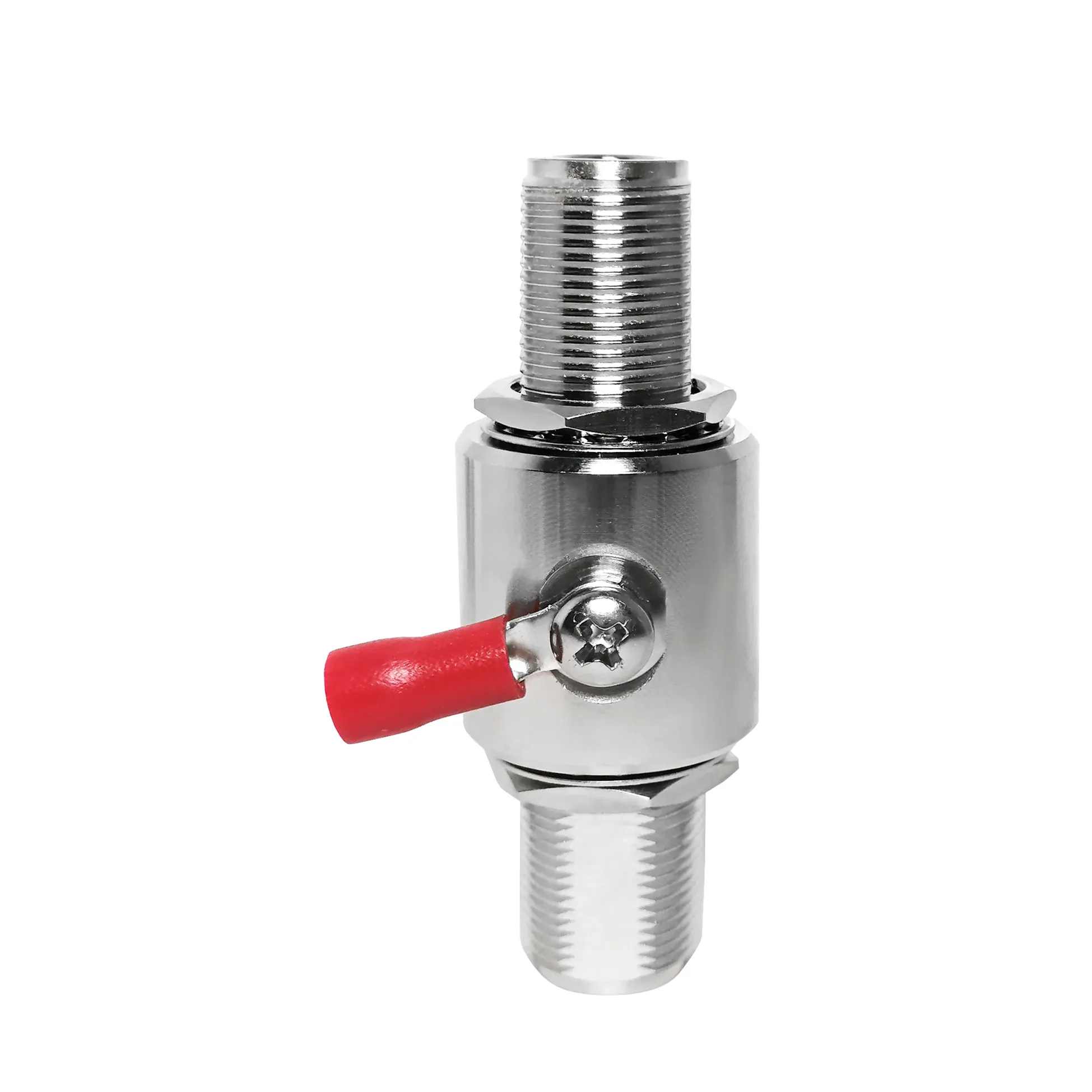
In contemporary microwave engineering, satellite communication payloads, and advanced wireless testing architectures, bridging disparate transmission line dimensions without degrading signal quality is an ongoing engineering challenge. Wideband radio frequency systems often couple heavy-gauge infrastructure cabling terminated with rugged Type N interfaces directly to compact, high-frequency circuit boards or test instrumentation utilizing miniature SMA ports. Executing this transition successfully requires a precision-engineered N-to-SMA adapter. Far more than a simple mechanical joiner, a high-performance N-to-SMA adapter dictates the return loss, phase stability, and operational bandwidth of the entire wideband RF interconnect chain.
As an industry-leading manufacturer,
Wideband RF Challenges in Inter-Series Transitions
Designing a robust wideband RF interconnect presents unique electromagnetic obstacles, particularly when spanning frequencies from direct current (DC) up to 18 GHz. As operating frequencies increase, the physical wavelength shrinks, making even microscopic internal geometric discontinuities significant sources of signal reflection.
-
Impedance Step Transitions: The Type N connector features a relatively large outer conductor diameter and an air-spaced or heavy PTFE dielectric, whereas the SMA interface is compact with a smaller dielectric boundary. Transitioning between these distinct geometries inside an N-to-SMA adapter requires a carefully tapered inner conductor and dielectric pocket. Without this precise internal profiling, abrupt impedance steps generate severe capacitive reactance.
-
Mode Propagation Limits: Higher-order propagation modes can emerge if the inner cavity of the coaxial RF adapter exceeds critical cutoff dimensions at upper microwave frequencies. Maintaining strict concentricity is vital to ensure that only the dominant transverse electromagnetic (TEM) mode propagates cleanly through the junction.
-
Bandwidth Continuity: A substandard N-to-SMA adapter often exhibits sharp resonance dips or reflection spikes at specific frequencies within a wideband sweep. Ensuring flat insertion loss from DC to 12.4 GHz or higher is a core requirement for modern instrumentation links.
High-Frequency Electrical Characteristics and Performance Metrics
To evaluate whether a specific N-to-SMA adapter is suitable for demanding wideband applications, engineers must analyze three primary electrical parameters during benchtop testing and system integration.
-
Voltage Standing Wave Ratio (VSWR): For a professional-grade N-to-SMA adapter, VSWR must remain exceptionally low across the entire operational band. A top-tier unit should maintain a VSWR of <= 1.15:1 up to 6 GHz and <= 1.25:1 up to 12.4 GHz, preventing power reflection from damaging sensitive transmitter amplifier stages.
-
Insertion Loss Management: Every component in a wideband RF interconnect contributes to total signal attenuation. Premium adapters utilize passivated stainless steel or nickel-plated brass bodies paired with gold-plated beryllium copper center contacts, keeping insertion loss below 0.15 dB per transition.
-
RF Shielding Effectiveness: External electromagnetic interference can easily corrupt low-level wideband signals. A robust coaxial RF adapter employs solid outer conductor walls and tight threaded coupling mechanisms to achieve shielding effectiveness values exceeding 90 dB.
Parameter Comparison: Standard Commercial vs. Precision Wideband Grades
To illustrate how specific manufacturing grades impact system performance, the following table compares basic commercial-grade units with high-performance wideband assemblies.
| Evaluation Metric | Standard Commercial Grade | Precision Wideband Grade (N-to-SMA adapter) |
| Operational Frequency Range | DC to 6.0 GHz | DC to 18.0 GHz |
| Maximum VSWR (at 12 GHz) | <= 1.45:1 | <= 1.22:1 |
| Insertion Loss | <= 0.35 dB | <= 0.12 dB |
| Center Contact Material | Phosphor Bronze with Gold Flash | Beryllium Copper with 50-inch Gold Plating |
| Body Construction | Nickel-Plated Brass | Passivated Stainless Steel / Gold-Plated Brass |
| Mating Durability | 500 mating cycles | 1000+ mating cycles |
Engineering Pitfalls and Real-World Implementation Case Study
Even with a high-quality N-to-SMA adapter, improper installation techniques or mechanical stress can severely compromise a wideband RF interconnect.
Common Engineering Pitfalls
-
Exceeding Torque Limits on the SMA Interface: Technicians accustomed to rugged Type N hardware frequently over-torque the coupling nut of an N-to-SMA adapter on the SMA side, stripping the delicate threads or shearing the female socket fingers.
-
Neglecting Mechanical Strain Relief: Hanging heavy flexible cabling directly off an unmounted inter-series adapter creates a cantilever bending moment, which places undue shear stress on the internal connector solder joints and degrades VSWR performance.
Real-World Telemetry Case Study
A defense electronics contractor developing an airborne wideband surveillance terminal experienced intermittent signal distortion during high-vibration flight testing. Diagnostic sweeps revealed that an unverified commercial coaxial RF adapter in the local oscillator chain suffered from micro-movement at the inner contact interface, causing severe phase noise spikes. Replacing the component with a ruggedized, precision-machined Worldpeak connector variant featuring stainless steel outer housing and captive center contacts eliminated the mechanical play, achieving stable signal transmission across all operational environmental profiles.
Worldpeak Quality Assurance and Manufacturing Rigor
Achieving absolute reliability in every N-to-SMA adapter requires strict adherence to advanced manufacturing protocols and comprehensive testing frameworks. At
-
Automated CNC Machining: Computer-numeric-controlled lathe operations maintain inner conductor concentricity and dielectric cavity tolerances within micron-level limits, eliminating high-frequency phase errors.
-
100% Vector Network Analyzer (VNA) Screening: Every production batch of our wideband RF interconnect components undergoes automated sweep testing to verify return loss, insertion loss, and VSWR compliance prior to packaging.
-
Environmental and Compliance Testing: In strict alignment with international quality standards, our adapters are subjected to thermal shock, salt spray corrosion testing, and mechanical durability screening to guarantee long-term field survivability.
By combining superior material science with uncompromising quality control, selecting the right N-to-SMA adapter ensures maximum signal integrity for your critical microwave infrastructure. Explore our core architectural framework and complete product catalog on our





