 EN

N-Type Coaxial Cable: 50Ω Runs for Microwave Links
Deploying reliable wireless communication infrastructure requires precision engineering at every single connection point across modern telecommunication networks. In high-frequency wireless networks, cellular backhaul architectures, satellite communications, and specialized radar systems, microwave links demand absolute, uncompromising signal integrity. When system engineers design outdoor transceiver connections or complex antenna feeder systems, selecting the proper transmission line is absolutely critical for long-term operational success. Utilizing a specialized N-Type coaxial cable engineered specifically for robust 50-ohm runs ensures minimum signal attenuation and maximum power transfer across demanding frequency bands. WORLDPEAK delivers advanced coaxial cable assembly solutions designed specifically to withstand harsh outdoor environments while supporting high-performance microwave links.
Understanding the precise electrical parameters, impedance stability, and mechanical tolerances of these assemblies helps procurement teams and RF engineers eliminate deployment bottlenecks and prevent costly field failures.
Electrical and Mechanical Demands of 50-ohm Runs in Microwave Links
Microwave communication networks operate across ultra-high frequencies, where even minor impedance mismatches can cause severe signal reflections, standing waves, and catastrophic data packet loss. Maintaining strict 50-ohm runs is the universal industry standard for radio frequency power transmission, as it ideally balances low signal attenuation with exceptionally high power-handling capabilities.
When deploying an N-Type coaxial cable in a high-frequency microwave link, engineers must evaluate several key physical and electrical characteristics to ensure long-term network reliability:
-
Characteristic Impedance Tolerance: Controlled strictly within a tight 50-ohm window to prevent Voltage Standing Wave Ratio (VSWR) spikes across multi-gigahertz frequency spectra.
-
Inner Conductor Integrity: Solid or stranded silver-plated copper conductors that minimize skin-effect resistance at elevated operational frequencies.
-
Dielectric Material Selection: Low-loss expanded polytetrafluoroethylene (PTFE) or cellular polyethylene dielectrics that reduce capacitance and velocity factor degradation.
-
Connector Interface Precision: Mechanically robust N-Type male and female interfaces equipped with gold-plated brass or beryllium copper contacts to maintain low insertion loss.
-
Thermal Expansion Management: Materials engineered to compensate for drastic ambient temperature shifts without distorting the internal geometry of the transmission line.
Shielding Effectiveness and Attenuation Control in Long Outdoor Runs
Outdoor microwave installations expose critical transmission lines to intense electromagnetic interference (EMI), radio frequency interference (RFI), and severe weather fluctuations over extended operational lifespans. A standard single-shield cable is frequently insufficient for long-distance 50-ohm runs connecting tower-mounted antennas directly to base station transceivers.
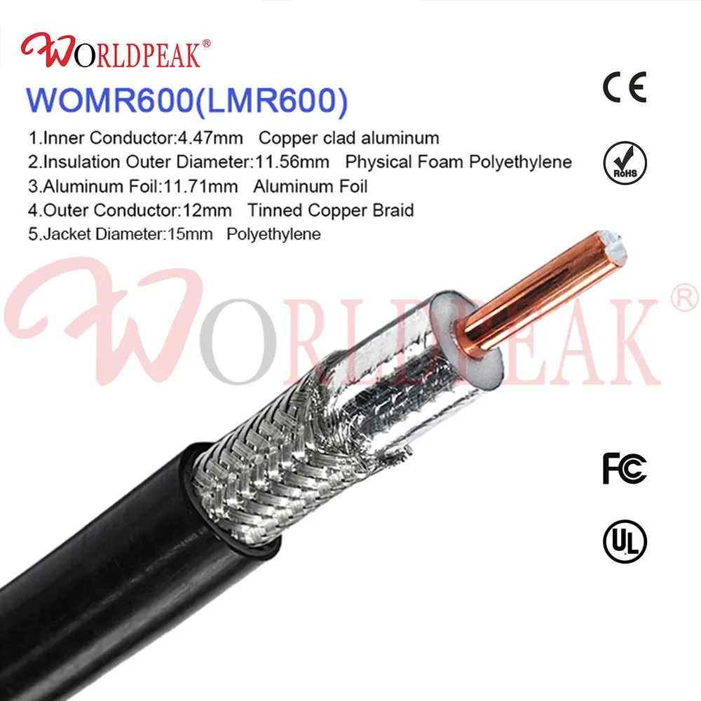
WORLDPEAK incorporates multi-layer shielding architectures into every N-Type coaxial cable assembly. By combining an inner bonded aluminum foil tape with an outer tinned copper braided shield achieving greater than 90% coverage, these assemblies effectively block external ambient noise and prevent internal signal leakage. This rigorous shielding design preserves high signal-to-noise ratios, ensuring that critical data transmitted across microwave links remains completely uncorrupted even in dense urban RF environments or heavy industrial zones. Furthermore, specialized UV-resistant outer jackets protect the internal dielectric and conductor from intense solar radiation and moisture ingress over decades of continuous outdoor deployment.
Parameter Comparison: Coaxial Transmission Solutions
To assist procurement professionals and system integrators in selecting the optimal interconnect architecture for their networks, the following table compares standard commercial assemblies with WORLDPEAK high-performance N-Type coaxial cable solutions designed for microwave links:
| Performance Parameter | Standard Commercial Cable | WORLDPEAK N-Type Coaxial Cable Solution |
| Operating Frequency Range | Up to 3 GHz | Up to 11 GHz (Optimized for Broadband Microwave Links) |
| Impedance Consistency | Nominal 50 ohm (plus/minus 3 ohm) | Precision 50 ohm (plus/minus 1 ohm) |
| Shielding Effectiveness | Greater than 60 dB | Greater than 90 dB (Multi-layer Foil and Braid) |
| Attenuation at 5 GHz | High loss over long cable runs | Ultra-low loss via low-dielectric constant foam |
| Outdoor Durability | Standard PVC jacket (UV degradation risk) | UV-resistant, weather-proof, halogen-free PE jacket |
Rigorous Factory Quality Control and Testing Protocols
Delivering faultless 50-ohm runs for mission-critical microwave links requires stringent, multi-stage quality control during the manufacturing process. Sub-par crimping, improper soldering, or poor dielectric stripping can instantly ruin the electrical performance of an entire coaxial cable assembly.
WORLDPEAK implements a comprehensive factory inspection protocol aligned with international quality standards:
-
Vector Network Analyzer (VNA) Testing: Every single N-Type coaxial cable assembly is thoroughly tested for insertion loss, return loss, and VSWR across its full operating frequency band before packaging.
-
Contact Resistance Verification: Precision micro-ohm meters verify that center pin and outer shell terminations exhibit minimal electrical resistance.
-
Environmental Stress Screening: Assemblies undergo rigorous thermal cycling and pull-force mechanical testing to guarantee structural endurance under high wind loads and extreme temperature swings.
-
Water Ingress and Seal Inspection: Pressurized leakage testing ensures that outdoor-rated assemblies maintain a hermetic seal against moisture and environmental contaminants.
By enforcing these rigorous testing checkpoints before mass dispatch, communication equipment manufacturers secure reliable field performance and eliminate unexpected maintenance overhead.
Integrating Into Your Network Architecture
Optimizing transmission lines for modern communication networks requires seamless collaboration between system designers and experienced manufacturing partners. Integrating custom-engineered N-Type coaxial cable assemblies into your infrastructure secures long-term signal stability and operational efficiency.
To explore our complete engineering capabilities and standard specifications for wireless infrastructure components, visit our main





