 EN

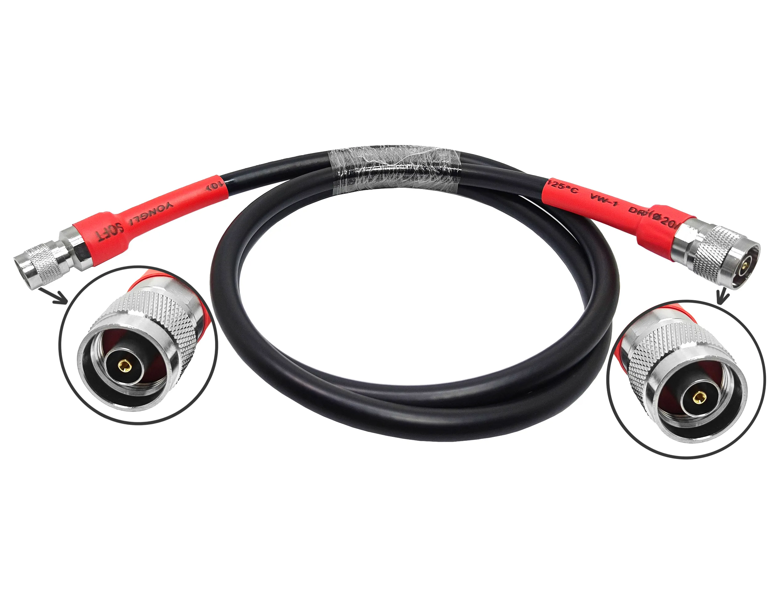
An n type coaxial cable assembly is far more than a flexible length of wire with two threaded end connectors. It functions as a precision-engineered radio frequency (RF) transmission path whose center conductor, solid dielectric, outer shield, connector termination, and physical routing must work together seamlessly. Whether deploying an outdoor cellular base station feeder, an indoor equipment rack patch link, or a laboratory test setup, selecting the proper n type coaxial cable assembly preserves signal integrity and system impedance. Conversely, installing an improper assembly introduces impedance mismatch reflections, excess insertion loss, and mechanical joint failure under environmental stress.
Engineering an RF interconnect begins at the signal path rather than simply selecting a connector from a catalog photo. System designers must define operational frequency boundaries first, establish allowable signal loss budgets second, and determine physical cable dimensions and weatherproofing ratings third. Following this structured evaluation prevents procurement errors where an n type coaxial cable assembly mates mechanically with front-panel hardware but fails to satisfy electrical or installation requirements.
Internal Coaxial Construction & Signal Path Geometry
A commercial n type coaxial cable assembly relies on four coaxial layers operating as a unified transmission structure:
-
Center Conductor: Transmits high-frequency RF current along its outer skin layer.
-
Dielectric Insulator: Maintains uniform concentric spacing between inner and outer conductors to preserve characteristic impedance.
-
Outer Shield / Conductor: Serves as the ground return path while blocking external electromagnetic interference (EMI).
-
Protective Outer Jacket: Shields internal metallic layers against moisture ingress, UV degradation, chemical exposure, and mechanical abrasion.
Precision N Type Coaxial Cable Assembly Architecture:
[Center Conductor (Skin-Effect Layer)] ---> [Dielectric Core (Impedance Spacer)] ---> [Outer Shield (EMI / Ground)] ---> [Outer Jacket (Environmental)]
The connector interface forms an integral extension of this coaxial geometry. A factory-terminated n type coaxial cable assembly maintains continuous shielding and constant dielectric ratios through the coupling nut. Selecting a larger center conductor reduces attenuation across long cable runs, whereas specifying a highly flexible stranded core simplifies tight cabinet routing.
System Impedance Matching: 50 Ohm vs 75 Ohm Parameters
RF wireless communications, cellular infrastructure, and test equipment utilize a 50 ohm characteristic impedance. Conversely, 75 ohm coaxial systems dominate video broadcast, cable television, and specialized signal distribution networks. Maintaining identical characteristic impedance across all interconnected components is critical; mating a 75 ohm cable into a 50 ohm RF path generates severe Voltage Standing Wave Ratio (VSWR) spikes and signal reflections.
| Selection Parameter | 50 Ohm RF Transmission Path | 75 Ohm Video & Distribution Path |
| Typical Application Context | Cellular base stations, LMR towers, Wi-Fi gateways, VNAs | Broadcast TV, HD-SDI video routing, CATV distribution |
| Primary System Check | Verify equipment and antenna ports match 50 ohm nominal rating | Verify source transmitter, cable, and loads match 75 ohm rating |
| Procurement Risk Factors | Ordering an n type coaxial cable assembly based solely on physical size | Assuming an inline adapter corrects an underlying impedance mismatch |
| Internal Geometry | Larger center pin diameter relative to outer conductor wall | Smaller center pin diameter to achieve higher dielectric ratio |
When submitting a Request for Quotation (RFQ), specify target impedance, cable length, operating bandwidth, and exact connector gender combinations for the complete n type coaxial cable assembly.
Attenuation, Shielding Efficiency, and Adapter Interconnects
Coaxial signal attenuation increases proportionally with operating frequency and physical route length. Long outdoor antenna runs require low-loss, larger-diameter cable architectures such as LMR-400 or corrugated feeder coax. For tight interior rack routing where space constraints dominate, compact 50 ohm cables provide essential flexibility without over-stressing internal printed circuit boards.
Inline Coaxial Adapter Topology:
[Equipment Interface (N-Type / SMA Port)] ---> [In-Series / Between-Series Inline Coaxial Adapters] ---> [Antenna Feeder Line (Main Transmission)]
When joining different cable sections or mating dissimilar equipment interfaces, selecting certified inline adapters is necessary:
-
In-Series Extensions: An n female to n female adapter joins two male cable terminations across bulkhead panels. While an n female to n female adapter provides physical connection, it cannot alter system impedance or restore lost signal amplitude.
-
In-Series Port Transitions: An n male to n male adapter connects two female panel jacks directly, functioning as a rigid inline jumper rather than an extension lead.
-
Between-Series Interconnects: An sma female to n male adapter bridges smaller sub-assemblies to heavy-duty feeder lines. An sma female to n male adapter must be rated for the highest operating frequency of the link to avoid introducing passive intermodulation (PIM).
Always verify port gender, thread engagement, and sealing specifications before inserting an n female to n female adapter, an n male to n male adapter, or an sma female to n male adapter into a mission-critical signal chain.
Field Installation & Quality Inspection Checklist
To maintain electrical performance and prevent mechanical degradation during installation, follow these standardized engineering procedures:
-
Adhere to Minimum Bend Radii: Enforce manufacturer dynamic and static bend radius limits. Bending an n type coaxial cable assembly beyond its design threshold deforms the internal dielectric, permanently altering impedance.
-
Eliminate Mechanical Side Loading: Route cables prior to final connector mating to prevent rotational twisting or lateral tension on cabinet bulkhead ports.
-
Protect Strain Relief Transitions: Position cable clamps, support brackets, and heavy-duty ties away from connector boots and heat-shrink strain relief sleeves.
-
Inspect Thread Integrity: Examine mating faces for debris, plating flakes, or pin misalignments prior to engagement. Hand-tighten coupling nuts before applying calibrated torque wrenches to prevent cross-threading.
-
Apply Weatherproofing Protocols: For outdoor installations, seal all exterior junctions—including any inline n female to n female adapter or sma female to n male adapter—using cold-shrink tubing or butyl rubber tape wrapping.
-
Execute Post-Installation Testing: Perform VNA sweep testing to verify VSWR, return loss, and insertion loss across the active frequency band.
Sourcing Verified Coaxial Assemblies
Specifying a production-ready n type coaxial cable assembly requires documenting frequency boundaries, insertion loss limits, jacket ratings (LSZH, Plenum, Direct Burial), and connector orientations (straight vs. right-angle). For specialized pre-terminated interconnects, system designers can evaluate the
By evaluating the complete RF signal path—from equipment transceiver ports through inline adapters to antenna terminations—engineering and procurement teams ensure every n type coaxial cable assembly delivers robust mechanical reliability and stable low-loss performance.





