 EN

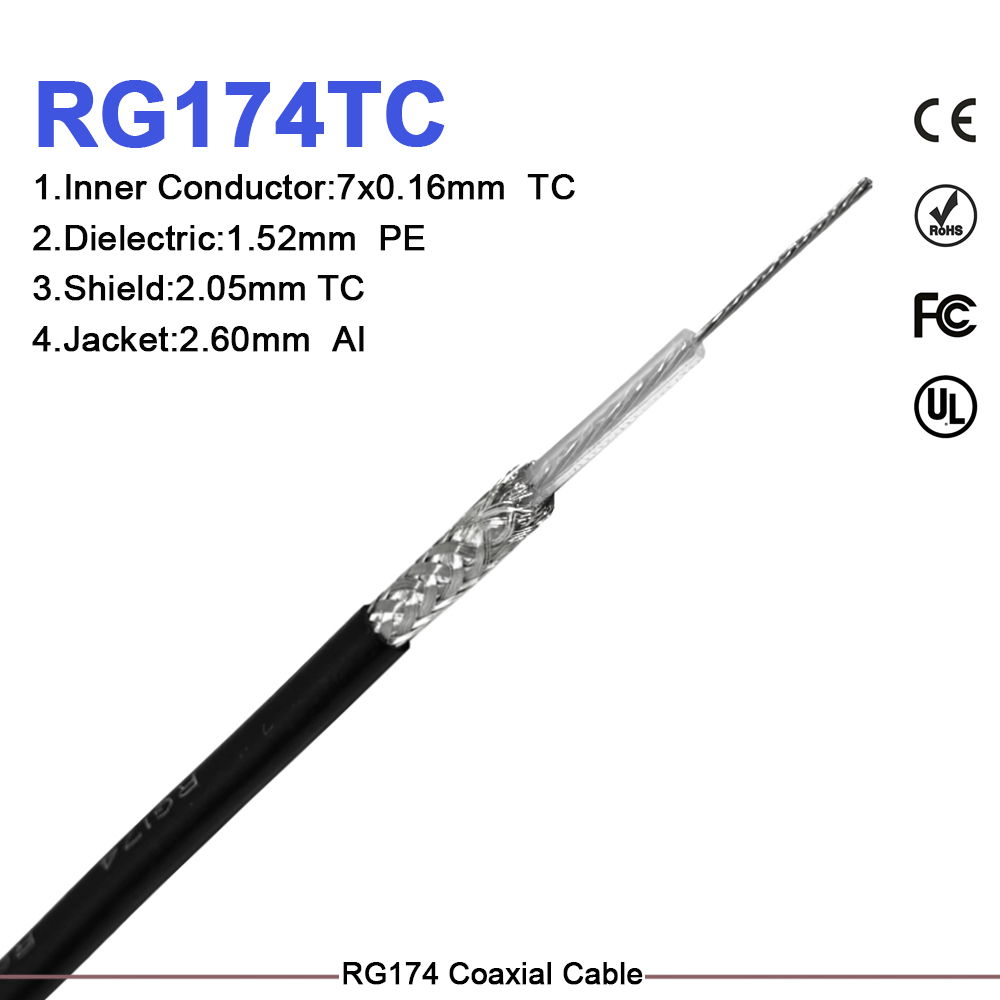
Selecting an rf cable for radar is far more than a routine connector decision. In modern pulse-doppler, phased-array, and maritime radar architectures, the coaxial cable assembly directly dictates transmitter power efficiency, receiver dynamic range, system signal-to-noise ratio, and long-term phase stability. An rf cable for radar that looks physically suitable on a workbench can easily degrade total system performance if it introduces unexpected attenuation, impedance mismatches, or thermal phase drift during field operation.
This engineering guide focuses on the practical subsystem-level requirements used by RF integration teams: defining the complete link budget, balancing insertion loss against frequency, selecting the appropriate mechanical shield construction, and coordinating adjacent active components.
Defining the Electrical Link Budget for Radar Systems
An rf cable for radar must be specified against the complete signal path budget rather than evaluated as an isolated transmission line. When calculating total insertion loss, engineering teams must evaluate attenuation per unit length at the highest expected operating frequency, including thermal drift margins across the full operating temperature range.
For example, an rf cable for radar configured as a short instrument jumper might exhibit negligible signal degradation at 2.4 GHz, yet produce unacceptable signal loss when scaled to a ten-meter antenna feed run operating at X-band (8–12 GHz) or Ku-band (12–18 GHz) frequencies.
Primary Electrical Parameters to Document:
- Insertion Loss Budget: Calculate cumulative attenuation across all cable runs and connector transitions at the maximum band limit. Margin at the upper frequency edge is critical because dielectric and conductor losses rise non-linearly with frequency.
- VSWR and Return Loss: Maintain strict 50-ohm impedance continuity through every interface. Abrupt geometry changes create internal reflections that increase Voltage Standing Wave Ratio (VSWR), reducing usable transmitter power transfer and causing potential high-power amplifier instability.
- Phase Stability and Matching: In phased-array radar, beamforming networks, and monopulse tracking systems, relative phase tracking between parallel cable channels is as crucial as power amplitude. Thermal phase coefficients and flexure-induced phase shifts must be tightly specified.
- Power Handling Capacity: Peak pulse power and continuous wave (CW) power limits must account for altitude derating, ambient temperature extremes, and mismatch conditions to prevent dielectric breakdown or thermal damage.
Coaxial Construction Comparison: Flexible, Semi-Rigid, and Corrugated Feeder Cables
Choosing the proper construction for an rf cable for radar depends on the mechanical routing environment, required bend radii, serviceability expectations, and phase stability requirements.
| Cable Construction | Primary Radar System Application | Key Advantage | Trade-off / Watch Point |
|---|---|---|---|
| Flexible Coaxial Cable | Service loops, rotating joints, elevated panels, moving radar antennas | High bend flex tolerance, easy field installation, simplified maintenance | Requires monitoring of phase repeatability, insertion loss under continuous flexing, and shield wear |
| Semi-Rigid Coaxial Cable | Fixed internal module links, power amplifier interconnects, precision test paths | Excellent shape retention, high phase stability, maximum shielding effectiveness | Requires precise 3D pre-formed routing drawings and careful handling during assembly to prevent denting |
| Corrugated Feeder Cable | Stationary long-distance feeder runs from transceiver shelters to mast towers | Lowest possible attenuation per meter, highly ruggedized outdoor protective jackets | Large outer diameter, strict minimum bend radius limits, specialized termination tooling required |
When evaluating commercial cable lines such as megaphase rf cables or similar high-performance assemblies, procurement and engineering teams should compare published attenuation curves, shielding effectiveness values, and mechanical bend ratings directly against their system drawing requirements. Selecting megaphase rf cables or equivalent high-reliability families ensures reliable shielding against external EMI, but exact specification control must still be maintained on the final procurement drawing.
Evaluating megaphase rf cables against project specifications allows engineers to confirm whether a standard commercial off-the-shelf cable family satisfies the thermal and phase stability limits of their radar front end. When comparing megaphase rf cables to custom options, verify that swept test data covers the full radar operating frequency.
Co-Locating Adjacent RF Components: Interfaces and Noise Control
An rf cable for radar does not operate in isolation; it directly connects active front-end components, passive signal distribution networks, and monitoring circuitry.
Integration with a Bias T RF Module
When incorporating a bias t rf component to inject DC power into a remote low-noise amplifier (LNA) along the main coaxial run, the central conductor of the rf cable for radar must carry combined DC current and high-frequency RF energy without thermal saturation or signal distortion.
The low-frequency isolation and power handling of the bias t rf unit must complement the cable's insertion loss profile to maintain optimal receiver sensitivity. In high-power transmitter legs, choosing a bias t rf interface with matching 50-ohm impedance minimizes return loss spikes across the operational band.
Noise Control with RF Schottky Diode Circuits
In radar power-monitoring, envelope detection, or receiver protection circuits utilizing an rf schottky diode, the high shielding effectiveness of the rf cable for radar prevents ambient electromagnetic interference (EMI) and transmitter leakage from corrupting delicate sensor signals.
Because an rf schottky diode operates on low threshold voltages, small amounts of coupled noise from nearby motors or digital power supplies can introduce measurement errors. High-integrity shielding in the coaxial path maintains a clean electromagnetic environment around the rf schottky diode circuit, ensuring precise RF power measurement and dependable threshold detection.
Worldpeak Cable Assemblies and Quality Verification
To ensure reliable performance in demanding naval, airborne, and ground radar installations, Worldpeak provides custom flexible and semi-rigid cable assemblies built to precise electrical and mechanical tolerances.
- Worldpeak SS402 Pre-Terminated Assembly: Designed for tight internal enclosure paths requiring excellent 50-ohm impedance matching, low VSWR, and dependable shielding up to 18 GHz.
- 1/2" Superflex Corrugated Copper Feeder Cable: Ideal for low-loss, weather-sealed main feeder runs connecting ground transceiver units to elevated radar antenna arrays.
Every high-reliability rf cable for radar supplied by Worldpeak can be provided with full swept insertion-loss and return-loss test reports, ensuring compliance with rigorous quality control standards and military-grade environmental requirements.
Procurement Checklist for Radar Coaxial Assemblies
To streamline sourcing and eliminate integration errors, procurement and engineering teams should follow this step-by-step checklist when specifying an rf cable for radar:
- Define Frequency and Power Limits: Specify the exact frequency band, maximum peak power, continuous power, and allowable attenuation budget.
- Lock Down 50-Ohm Continuity: Require swept return-loss and VSWR verification for all pre-terminated connector interfaces.
- Select Mechanical Construction: Choose flexible, semi-rigid, or corrugated constructions based on physical routing constraints and service loop needs.
- Specify Environmental Protection: Detail operating temperature range, vibration limits, moisture sealing, UV resistance, and chemical exposure conditions.
- Establish Phase Matching Tolerances: Define absolute or relative phase tracking requirements for multi-channel phased-array installations.
- Enforce Traceable Quality Records: Partner with established manufacturers like Worldpeak to obtain verified test documentation prior to full volume production release.





