 EN

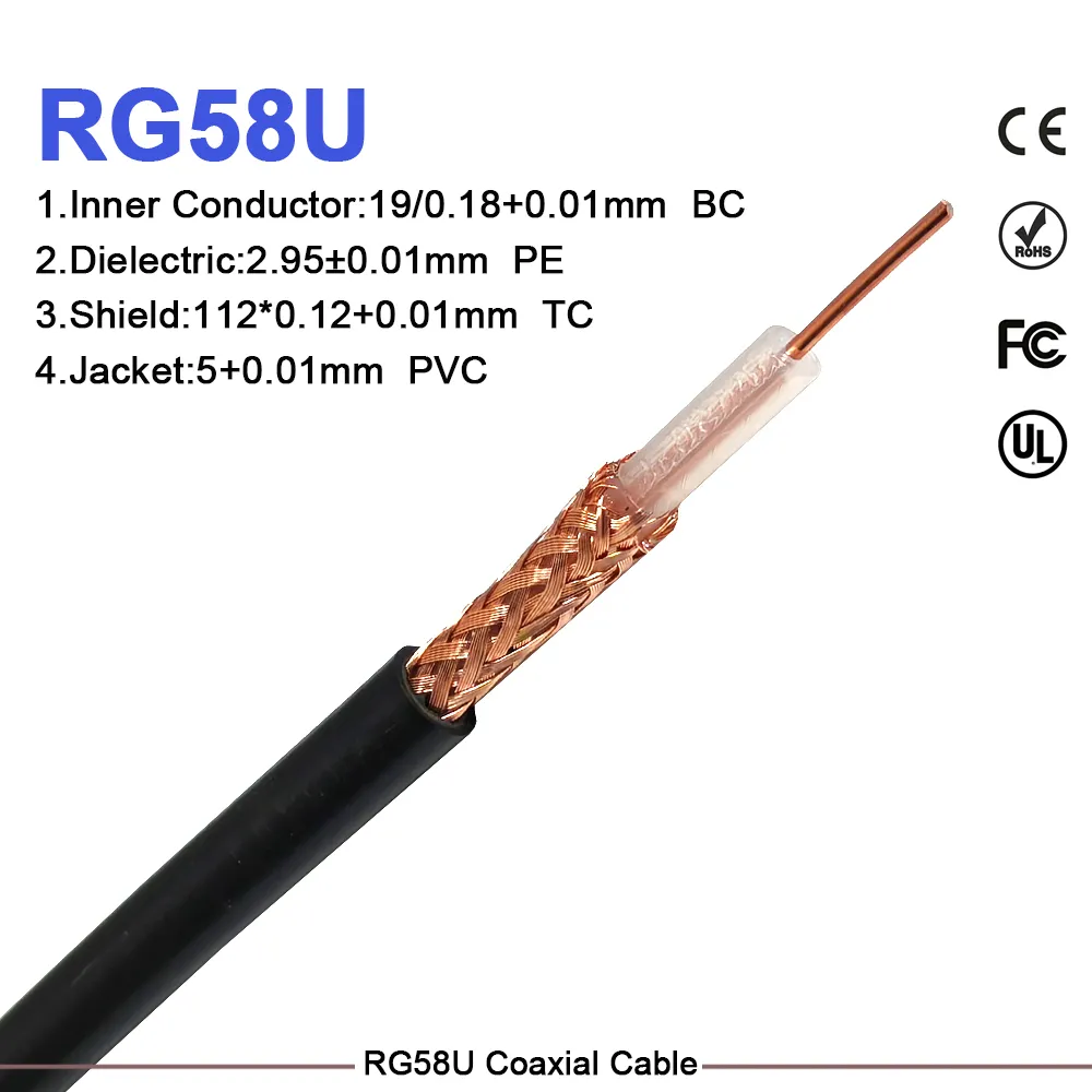
When an RF cable run looks straightforward on a wiring schematic, procurement teams are often tempted to select components based on physical diameter, price, or connector type alone. In radio frequency engineering, this shortcut creates severe system-level signal degradation. The transmission line, equipment ports, antenna, and connector interfaces must function as an integrated, impedance-matched path. An rg58 coaxial cable is a highly flexible 50 ohm coaxial cable option widely deployed for low-power RF interconnections, short ham radio coax cable patch feeds, test bench leads, and BNC-terminated interconnects. It also appears around video security setups, though it is not an automatic replacement for the 75-ohm coaxial cable typically required for baseband analog video distribution.
As an RF systems engineer, optimizing a signal path begins with verifying the system impedance requirement, evaluating operating frequency against distance attenuation, and selecting the proper jacket compound, shield coverage, and connector format. This systematic selection workflow prevents a costly purchasing error: acquiring a coaxial cable assembly that fits physically but introduces extreme insertion loss or VSWR reflections where the RF signal path can least tolerate it.
Technical Construction of an RG58 Coaxial Cable
Every rg58 coaxial cable relies on precise physical geometry to establish its electrical properties. The assembly consists of four primary concentric layers:
-
Center Conductor: Solid or stranded copper core carrying the main signal.
-
Dielectric Insulator: Maintains precise radial spacing between the conductor and shield.
-
Metallic Shield: Braided or foiled barrier preventing electromagnetic interference (EMI) and RF leakage.
-
Outer Jacket: Protective outer sheath guarding against physical wear and weather exposure.
In a standard rg58 coaxial cable, the nominal characteristic impedance is calibrated to 50 ohms. This specific value matches the input/output impedance of most commercial RF test instruments, transceivers, mobile radios, antenna tuners, and passive distribution components.
Manufacturing specifications and shielding grades vary significantly across suppliers. Before approving a production purchase order, buyers must verify conductor material (bare copper vs. tinned copper vs. copper-clad steel), shield braid density (typically 70% to 95%), jacket rating (PVC, PE, or LSZH), thermal limits, and real-world signal attenuation figures across the targeted operating spectrum.
50Ω vs. 75Ω: Matching System Requirements to Avoid Mismatch Losses
Selecting between a 50-ohm and a 75-ohm transmission path is fundamentally an impedance-matching decision governed by maximum power transfer and signal attenuation laws. A 50-ohm transceiver port, power amplifier, or spectrum analyzer must pair with a 50 ohm coaxial cable path to maximize power transfer and minimize Voltage Standing Wave Ratio (VSWR). Conversely, standard 75-ohm baseband video cameras, broadcast displays, and CATV distribution systems require 75-ohm cabling (such as RG59 or RG6) to maintain signal clarity over long runs.
Connecting a 50-ohm rg58 coaxial cable into a 75-ohm video circuit creates an impedance boundary mismatch. A portion of the transmitted signal reflects back toward the source, causing ghosting in video feeds or signal degradation in RF networks.
| Selection Metric | 50Ω RG58 Cable Configuration | 75Ω Standard Video Cable Configuration |
| Primary System Interface | Transceivers, 50Ω RF antennas, test leads, wireless nodes | Analog CCTV cameras, baseband video, broadcast hardware |
| Initial Engineering Check | Confirm 50Ω output port on radio, amplifier, or test unit | Confirm 75Ω BNC/F-type video inputs, recorders, and monitors |
| Primary Mismatch Risk | High VSWR, standing waves, reduced power transfer | Signal reflections, video ghosting, impedance mismatch loss |
| Focus Metrics | Operating frequency, shield density, flexibility, loss/100ft | Low attenuation at video frequencies, 75Ω termination |
For CCTV and video security projects, engineering teams must clarify whether the transmission architecture is an analog 75-ohm video line or a 50-ohm wireless backhaul/antenna extension. Specify these distinct runs separately in your bill of materials to maintain proper signal integrity across all nodes.
Deploying RG58 for Ham Radio Feeds and Short RF Interconnects
For amateur radio operators, an rg58 coaxial cable is an effective choice when the system calls for 50 ohms and the overall cable length is short enough that signal attenuation remains manageable at HF and VHF bands. The flexible stranded core of an rg58 coaxial cable proves exceptionally valuable when connecting transceivers inside vehicle cabins, routing behind cramped equipment racks, or handling portable ham radio coax cable field setups where cable leads are coiled and deployed repeatedly.
-
50Ω Transceiver Output connects directly to a Short RG58 Patch Cable (<10 meters), delivering low insertion loss directly to the Antenna or Tuner.
However, attenuation scales higher as operating frequencies increase or cable lengths extend:
-
HF Band (3-30 MHz): Low loss, making RG58 an ideal and highly flexible choice.
-
VHF Band (144 MHz): Moderate loss, fully acceptable for short patches and mobile jumpers.
-
UHF Band (440+ MHz): High loss, requiring a upgrade to larger low-loss options like LMR200 or LMR400 for longer runs.
When designing longer 50-ohm antenna feed lines, engineers must evaluate attenuation charts at the specific operating frequency. For extended outdoor runs or higher frequency bands, upgrading to a larger low-loss cable—such as an LMR400 equivalent—delivers a superior 50-ohm path with drastically reduced decibel loss per foot, provided the physical routing accommodates its larger bend radius.
Connector Integration and Assembly Considerations
Selecting the proper coaxial cable assembly requires looking beyond the mechanical cable jacket diameter. Procurement teams must verify interface family (BNC, SMA, N-Type, TNC, UHF/PL-259), connector gender, contact plating, crimp/solder style, and mating tolerances at both ends of the run.
A complete coaxial cable assembly featuring direct factory-terminated connectors eliminates the signal degradation associated with using excessive inline adapters. While a thread-on adapter or converter solves temporary interface discrepancies on a test bench, every additional connector interface adds insertion loss and creates a potential mechanical failure point. In high-frequency, mobile, or high-vibration environments, specified factory-terminated assemblies ensure consistent RF performance and long-term mechanical stability.
For compact internal equipment builds where space is restricted, miniature coaxial cables (such as RG178 or RG174) offer tight bend radii for internal board-to-board routing. However, these thin micro cables should not replace a standard rg58 coaxial cable in external interconnect applications, as their tiny conductors exhibit significantly higher attenuation and lower power-handling capabilities.
Protecting Physical Geometry and Bend Radius
Coaxial transmission lines rely on uniform physical geometry to maintain a consistent 50-ohm characteristic impedance. Crushing, kinking, overtightening cable ties, or forcing sharp bends distorts the dielectric insulation and alters center conductor spacing, triggering localized impedance shifts and internal signal reflections.
-
Correct Routing: Smooth, gradual curves preserve dielectric geometry and maintain a steady 50Ω impedance.
-
Incorrect Routing: Sharp kinks, crushed jackets, or overtightened zip ties deform the dielectric core, causing sudden VSWR spikes and signal reflection.
Key handling rules for installation include:
-
Calculate Route Distances: Measure precise routing paths, including vertical cabinet drops, bulkhead turns, and an adequate service loop allowance.
-
Respect Bend Radius: Maintain smooth bends that strictly adhere to the manufacturer's specified minimum bend radius (typically 5x to 10x the cable outer diameter).
-
Provide Strain Relief: Secure cable runs near connector entry points so the electrical joint does not support unsupported hanging weight.
-
Avoid Mechanical Stress: Do not crush cables under heavy zip ties or clamp them directly against sharp metal edges inside equipment enclosures.
-
Label Assembly Endpoints: Clear labeling on every coaxial cable assembly run with impedance, line designation, and target port simplifies installation and long-term system maintenance.
B2B Procurement Checklist for RG58 Cable Orders
A comprehensive Request for Quotation (RFQ) describes system requirements rather than simply listing a generic cable part number. To streamline procurement and prevent order revisions, include the following technical metrics in your initial request:
-
System Impedance: Specify 50-ohm impedance to ensure compatibility with RF transceivers, test instruments, and antenna systems.
-
Frequency Range: State the target operating frequency (e.g., HF, VHF, UHF, 2.4 GHz) to allow factory engineers to evaluate attenuation limits.
-
Assembly Length and Tolerances: Define exact tip-to-tip length requirements, along with acceptable length tolerances for production runs.
-
Connector Configurations: Identify interface families (BNC, SMA, N-type, PL-259) and genders for both End A and End B to ensure direct connectivity without extra adapters.
When sourcing factory-built solutions, reviewing engineered product lines like the WORLDPEAK pre-terminated rg58 coaxial cable program provides fully tested 50-ohm jumper options for commercial communications, test benches, and industrial wireless systems.
Conclusion: Engineering Reliable 50-Ohm Signal Paths
The rg58 coaxial cable remains an industry standard for flexible, short-run 50 ohm coaxial cable applications, particularly in ham radio coax cable setups, RF test leads, and wireless communications links. Its practical value stems from maintaining precise impedance matching across 50-ohm equipment interfaces—not from treating all coaxial cables as interchangeable parts.
By verifying system impedance upfront, checking frequency attenuation over total run distance, selecting factory-terminated connectors, and preserving minimum bend radius during installation, engineers and buyers ensure a robust, low-loss transmission path that delivers long-term operational reliability.





