 EN

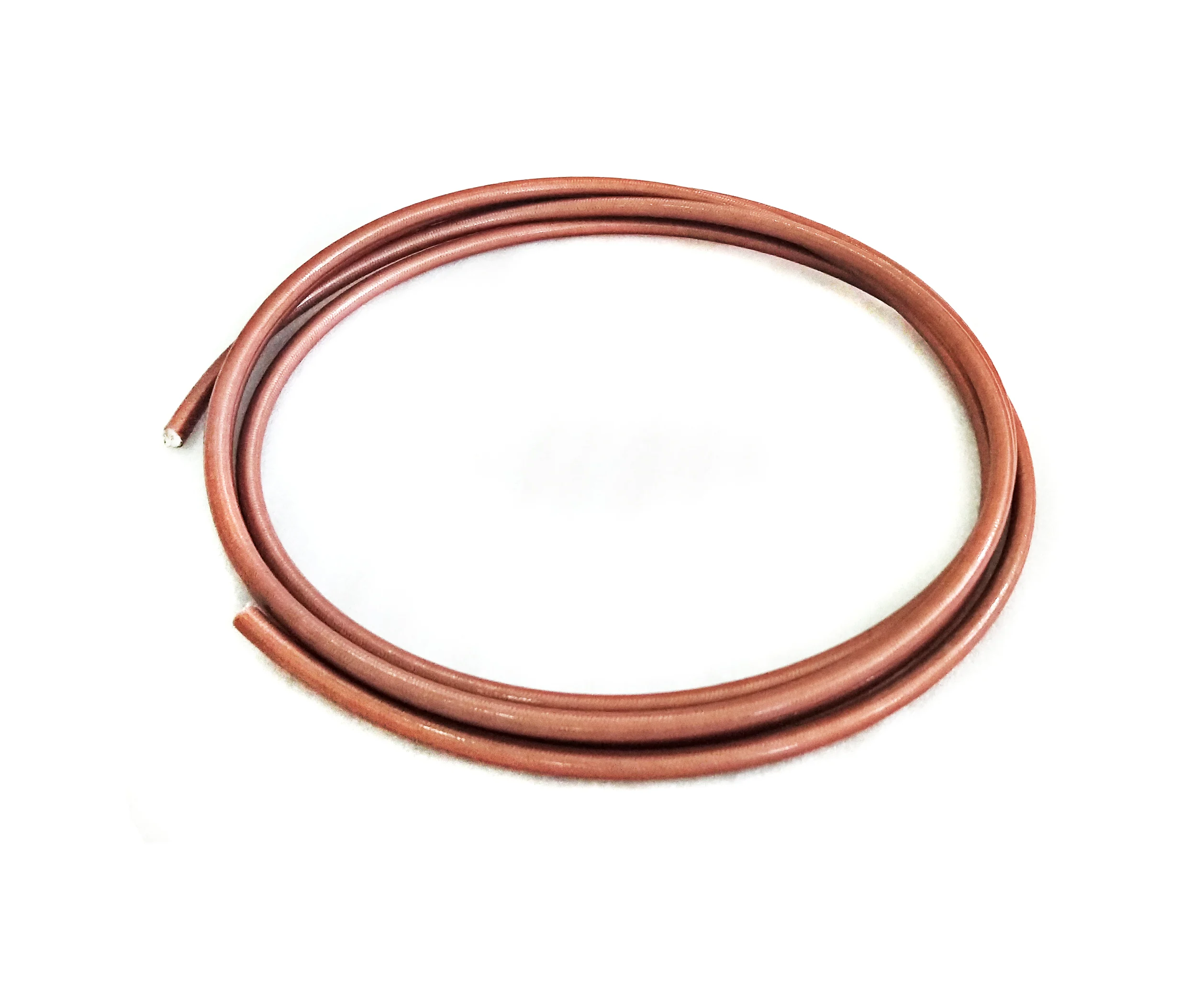
When designing high-power radio frequency (RF) broadcast networks, military radar installations, particle accelerators, and industrial microwave heating systems, selecting the appropriate transmission line medium is critical to overall system efficiency and long-term operational integrity. Among the available transmission line options, a rigid coaxial cable stands out as the ultimate solution for demanding applications requiring ultra-low signal attenuation, high power handling capability, and uncompromising mechanical durability. Unlike flexible or semi-rigid alternatives that rely on thin braided shields and continuous solid dielectric jackets, a rigid coaxial cable features solid, unbending outer and inner metal tubes. This unique physical architecture provides exceptional structural stability, superior electromagnetic shielding effectiveness, and unmatched thermal dissipation performance under continuous high-power loads. Worldpeak RF Connectors has engineered advanced rigid coaxial cable systems specifically designed to address the complex thermal, mechanical, and electrical challenges of modern high-power RF infrastructure.
Technical Deep Dive: Thermal Dissipation and Loss Reduction Mechanisms
In high-power RF transmission applications, thermal management represents one of the most critical design challenges. As continuous wave (CW) or high-duty-cycle pulsed power levels scale into tens or hundreds of kilowatts, internal electrical resistance and dielectric loss inevitably generate significant thermal energy within the line. In standard flexible cables, this heat becomes trapped by outer insulating jackets, leading to thermal breakdown, mechanical deformation, impedance drift, and eventual catastrophic failure. A rigid coaxial cable mitigates these risks through advanced conductor geometry and superior thermal conduction pathways.
Structurally, a high-quality rigid coaxial cable is engineered around three core components arranged in a precise concentric layout:
-
Outer Conductor: A high-purity, seamless heavy-walled copper or aluminum outer tube that provides robust structural support and superior ambient heat radiation.
-
Dielectric Core: A low-loss air-dielectric space supported by precision-machined PTFE (Teflon) disk spacers or helical insulators, maintaining exact center conductor alignment with minimal signal absorption.
-
Inner Conductor: A high-conductivity silver-plated copper rod or thick-walled tube designed to carry maximum RF current with minimal skin-effect resistance.
Because air exhibits a dielectric constant close to 1.0 and near-zero dielectric loss, the total insertion loss within a rigid coaxial cable is substantially lower than that of solid-dielectric flexible cables of equivalent outer diameter. Furthermore, thermal dissipation in a rigid coaxial cable relies on direct metallic conduction and internal radiant transfer. Heat generated on the inner conductor transfers across the air gap and PTFE spacers to the heavy-walled outer conductor, where it dissipates directly into the surrounding ambient air. Worldpeak RF Connectors optimizes the air-to-dielectric ratio in every rigid coaxial cable assembly to minimize voltage standing wave ratio (VSWR) reflections and localized hot spots, ensuring that thermal accumulation remains safely below critical thresholds during high-power continuous wave operations.
Parameter Comparison: Rigid vs. Semi-Rigid vs. Flexible Coaxial Cables
To provide clear engineering guidance when choosing between transmission line technologies, the table below compares key electrical, thermal, and structural parameters across standard coaxial configurations.
| Engineering Parameter | Rigid Coaxial Cable | Semi-Rigid Coaxial Cable | Flexible Coaxial Cable |
| Power Handling Capacity | Extremely High (Multi-Kilowatt to Megawatt CW) | Moderate to High (Hundreds of Watts to Kilowatts) | Low to Moderate (Tens to Hundreds of Watts) |
| Insertion Loss / Attenuation | Lowest available (Optimized air-dielectric design) | Low (Solid PTFE or expanded PTFE core) | Moderate to High (Solid PE/PTFE dielectric core) |
| Shielding Effectiveness | >120 dB (Solid seamless outer conductor tube) | >100 dB (Seamless metal outer tubing) | 85 - 90 dB (Single or double metallic braided shield) |
| Thermal Dissipation Rate | Superior (Direct copper conduction to ambient air) | Moderate (Thinner outer tube wall dimensions) | Poor (Outer jacket creates thermal insulation barrier) |
| Mechanical Bend Radius | Fixed straight sections (Requires rigid elbows) | Formable once with precision bending tools | Highly flexible (Repeated flexing permitted) |
| Primary Deployment Areas | Transmitter outputs, broadcast towers, radar feeds | Internal equipment chassis, sub-assemblies | Mobile test setups, patching, jumper interconnects |
Real-World Engineering Case Study: High-Power UHF TV Broadcast Station Retrofit
To illustrate the real-world operational benefits of integrating a rigid coaxial cable system in demanding environments, consider a comprehensive feedline retrofit conducted by Worldpeak RF Connectors for a regional UHF television broadcast facility operating a 50 kW solid-state transmitter.
The broadcast station previously utilized large flexible corrugated copper feedlines along a 150-meter vertical tower run. Over time, environmental temperature fluctuations caused dielectric degradation, elevated VSWR, severe signal attenuation, and thermal drift, resulting in frequent automatic transmitter power throttling during peak summer afternoons. The engineering team selected a complete retrofit utilizing Worldpeak 3-1/8 inch 50-ohm rigid coaxial cable feedline runs equipped with silver-plated inner conductors and heavy-duty gas-pressurized flanged coupling systems.
The performance metrics recorded following the successful installation highlight the dramatic improvements achieved:
| Performance Parameter Measured | Legacy Flexible Cable System | Worldpeak Rigid Coaxial Cable System | Net Improvement / Result |
| Insertion Loss (Total Run) | High attenuation over 150m | Minimized attenuation | 35% overall reduction in line loss |
| Transmitter Interface Temperature | Elevated thermal readings | Stable ambient conduction | 18°C lower operating temperature |
| Return Loss / VSWR Stability | Fluctuating under weather stress | Excellent impedance stability | Maintained >32 dB across UHF band |
| Unplanned Transmitter Downtime | Frequent thermal shutdowns | Zero weather-related trips | 100% reliable 24/7 broadcast uptime |
By replacing the degraded flexible line with Worldpeak's high-efficiency rigid coaxial cable, the broadcast station achieved a 35% reduction in overall transmission line loss, delivering significantly higher effective radiated power (ERP) to the antenna array. Furthermore, skin-effect optimization and air-dielectric thermal management reduced operating temperatures at the main transmitter interface flange by 18°C during high ambient summer conditions. This successful deployment eliminated thermal shutdown risks, stabilized output impedance, and guaranteed 24/7 continuous broadcast operations.
Quality Control and Manufacturing Standards at Worldpeak
Delivering uncompromising reliability in high-power applications requires adherence to strict international manufacturing frameworks and rigorous quality assurance protocols. At Worldpeak RF Connectors, every rigid coaxial cable section is produced in accordance with ISO 9001 quality management systems and meets or exceeds relevant IEC and MIL-PRF international technical specifications. The manufacturing and inspection workflow follows a meticulous sequence:
-
Raw Material Inspection and Chemical Analysis: High-purity oxygen-free copper tubing undergoes rigorous spectrochemical testing to verify electrical conductivity levels exceeding 100% IACS (International Annealed Copper Standard) before any rigid coaxial cable enters production.
-
Precision Machining and Concentricity Control: Automated multi-axis CNC machinery processes inner conductors, outer flanges, and connector adapters. Tight machining tolerances within plus-or-minus 0.01 mm ensure consistent characteristic impedance along the entire length of the rigid coaxial cable.
-
Surface Electroplating and Passivation: Inner conductors undergo high-purity electro-silver plating to maximize skin-effect conductivity at high frequencies, while outer copper surfaces receive specialized passivation treatments to resist environmental oxidation and salt spray corrosion.
-
Comprehensive RF and Pressure Testing: Every finished rigid coaxial cable assembly undergoes 100% automated vector network analyzer (VNA) sweep testing for return loss, insertion loss, and VSWR (consistently maintaining VSWR below 1.05:1 over specified operational bandwidths). For pressurized gas-filled installations, lines undergo dry nitrogen pneumatic leak testing to verify seal integrity at flanged junctions.
Key Selection Criteria for Engineering Teams
When specifying a rigid coaxial cable system for high-power installations, design engineers must evaluate several key physical and electrical criteria to ensure optimal system compatibility:
-
Frequency Range and Cutoff Frequency: Ensure the selected rigid coaxial cable diameter supports the operating frequency without introducing higher-order waveguide modes.
-
Peak and CW Power Ratings: Account for ambient operating temperatures, altitude derating factors, and maximum expected VSWR spikes when selecting line dimensions.
-
Pressurization Requirements: For outdoor or high-voltage applications, select gas-barrier rigid coaxial cable assemblies that allow dry air or nitrogen pressurization to prevent internal moisture condensation and flashover arcing.
-
Thermal Expansion Compensation: Incorporate sliding inner conductor connectors and spring-loaded expansion joints in long vertical runs to absorb thermal expansion and contraction cycles without applying mechanical stress to transmitter output ports.
Conclusion and Strategic Next Steps
In conclusion, optimizing high-power RF transmission networks demands rigorous consideration of thermal dynamics, dielectric efficiency, precision machining, and strict manufacturing quality standards. Integrating a professionally engineered rigid coaxial cable solution effectively safeguards signal integrity, minimizes costly power losses, protects sensitive transmitter equipment, and maximizes total operational uptime across broadcast, radar, and industrial RF installations.
For a broader overview of industry frameworks, multi-frequency design principles, and complete line component catalogs, explore our comprehensive pillar guide on





