 EN

90-Degree Coax Connector: Right-Angle RF Solutions
2026/10/19
Choose a 90 degree coax connector with practical guidance on RF interfaces, mounting styles, impedance, and tight-space routing.
2026/10/16
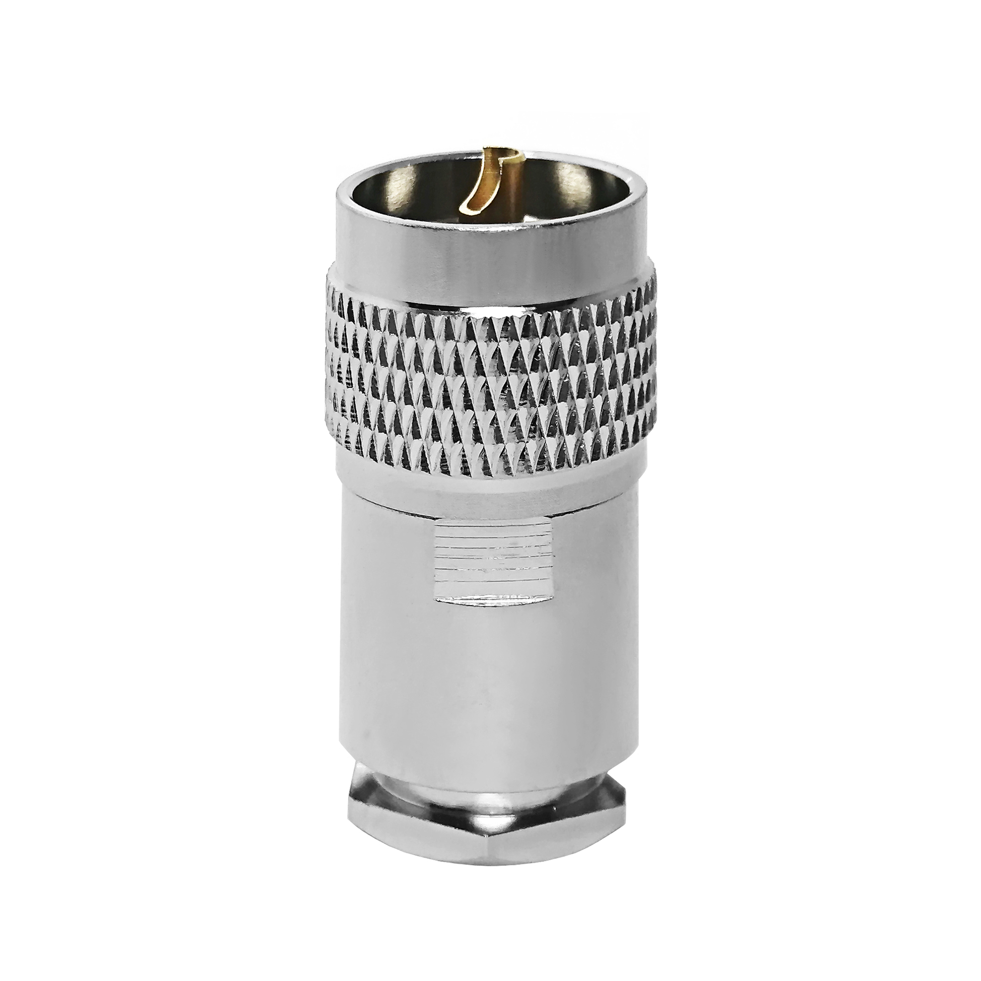
When designing high-frequency RF systems, every single component matters. Engineers often focus heavily on active components like amplifiers and oscillators, yet signal degradation frequently occurs at the interconnection level. Selecting the right MCX connector adapter is a critical decision that directly influences signal integrity, insertion loss, and Voltage Standing Wave Ratio (VSWR). In modern telecommunications, GPS modules, and high-frequency test equipment, utilizing a substandard or incorrectly matched MCX connector adapter can lead to severe signal reflection and data packet loss.
As a specialized manufacturer,
Operating in high-frequency spectrums (typically ranging from DC up to 6 GHz for standard MCX interfaces) requires strict adherence to electrical specifications. When evaluating an MCX connector adapter, engineers must closely examine impedance matching, frequency range, and VSWR performance.
Characteristic Impedance: Most high-frequency RF systems operate at a nominal impedance of 50 Ohms. Using a 50 Ohm MCX connector adapter is essential to prevent signal reflection. Although 75 Ohm variants exist for video applications, mixing them in high-frequency data links causes severe impedance mismatches.
VSWR (Voltage Standing Wave Ratio): For high-frequency applications, a low VSWR is paramount. A high-quality MCX connector adapter should maintain a VSWR of 1.15:1 to 1.25:1 up to 6 GHz. Lower VSWR ensures that maximum power is transmitted through the junction rather than reflected back into the source.
Insertion Loss: At frequencies above 3 GHz, insertion loss accumulates rapidly. Selecting an MCX connector adapter with gold-plated center contacts minimizes resistive losses and ensures stable high-frequency performance over extended operational lifespans.
Electrical performance is heavily dependent on mechanical precision. The physical dimensions and material selection of an MCX connector adapter dictate its durability, mating reliability, and resistance to environmental stressors.
Contact Material and Plating: High-frequency currents travel primarily on the outer skin of conductors (skin effect). Therefore, surface plating is critical. Premium options utilize beryllium copper for center pins, providing superior spring elasticity and contact force. Gold plating (minimum 30 micro-inches over nickel barrier) prevents oxidation and maintains low contact resistance.
Body Construction: The outer shell of a reliable MCX connector adapter is typically machined from high-grade brass or stainless steel. Stainless steel adapters offer enhanced mechanical durability and corrosion resistance for harsh industrial environments, while brass provides an optimal balance of cost and machinability for standard telecommunication setups.
Mating Mechanism: The snap-on locking design of an MCX connector adapter saves valuable PCB real estate compared to threaded SMA types. However, engineers must verify that the latching mechanism maintains retention force even after hundreds of mating cycles, ensuring reliable performance in modular test racks.
To better understand how specific design grades impact performance, the following table compares standard commercial-grade units with high-performance variants typically deployed in professional RF environments.
| Performance Metric | Standard Commercial Grade | High-Frequency Grade (MCX connector adapter) |
| Max Frequency Range | DC to 3.0 GHz | DC to 6.0 GHz |
| VSWR (at 3 GHz) | <= 1.35:1 | <= 1.20:1 |
| Insertion Loss | <= 0.30 dB | <= 0.12 dB |
| Center Contact Material | Phosphor Bronze / Gold Flash | Beryllium Copper / Thick Gold Plating |
| Durability (Cycles) | 500 mating cycles | 1000+ mating cycles |
| Operating Temperature | -40°C to +85°C | -55°C to +155°C |
Even with a top-tier MCX connector adapter, improper installation or mismatched pairing can compromise an entire RF subsystem.
Ignoring Cable Dielectric Compatibility: Forcing an MCX connector adapter designed for semi-rigid micro-coax onto flexible braided cables introduces mechanical stress and air gaps, causing impedance spikes.
Over-Torquing or Misalignment: Although snap-on connectors do not use wrenches, axial misalignment during blind-mate installation can damage the delicate female socket fingers inside the MCX connector adapter.
A recent deployment of high-frequency wireless asset trackers experienced intermittent packet loss during thermal cycling. Engineers discovered that an unverified MCX connector adapter used in the antenna feedline suffered from thermal expansion mismatch, leading to micro-gaps at the center contact interface. Replacing it with a high-precision, precision-machined MCX connector adapter featuring beryllium copper contacts resolved the thermal drift issue, achieving a stable VSWR of 1.18:1 across the entire operational temperature range.
Ensuring that every MCX connector adapter performs flawlessly under demanding high-frequency conditions requires a strict, transparent quality control protocol. At
Automated CNC Machining: Precision lathe operations maintain inner conductor concentricity within micrometric tolerances, preventing high-frequency phase distortion.
100% Network Analyzer Testing: Every production batch of our high-frequency MCX connector adapter undergoes vector network analyzer (VNA) sweeping to verify return loss, insertion loss, and VSWR compliance before packaging.
Environmental and Compliance Screening: In strict alignment with international quality standards, our components are tested for salt spray corrosion resistance, thermal shock endurance, and are fully RoHS and REACH compliant.
By combining robust material science with uncompromising testing regimes, choosing the right MCX connector adapter ensures long-term reliability for your critical RF infrastructure. Explore our core architectural framework and full product catalog on our

2026/10/19
Choose a 90 degree coax connector with practical guidance on RF interfaces, mounting styles, impedance, and tight-space routing.

2026/10/18
Choose rf semi-rigid cable by loss, shielding, impedance, and bend geometry for precise RF and microwave assemblies.

2026/10/17
Choose a 50 ohm RG cable by type, impedance, connectors, jacket, routing needs, and indoor or outdoor installation conditions.

2026/10/16
Compare rg214 coax construction, 50-ohm uses, shielding, attenuation, installation limits, and practical cable selection steps.

2026/10/15
In RF system design, there is a critical threshold where jumper cables like LMR-195 or LMR-200 become too lossy for reliable signal transmission, yet heavy-duty cables like LMR-400 are overkill for the distance and budget. LMR-240 exists precisely in...

2026/10/14
When designing RF systems, engineers often face a trade-off: choose a thin, flexible cable with higher signal loss, or a thick, low-loss cable that is difficult to route in tight spaces. LMR-200 coaxial cable was engineered to solve this exact dilemm...