 EN

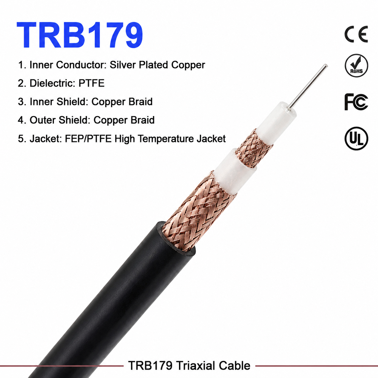
In the architecture of modern microwave systems, wireless instrumentation, and high-speed telecommunication networks, the transmission medium connecting active RF components dictates overall system reliability. As operating frequencies push well into the gigahertz spectrum, standard hook-up wires fail due to excessive signal attenuation and electromagnetic interference. Deploying a precision-engineered SMA coax cable is essential for maintaining signal integrity, phase stability, and low insertion loss. Whether configuring benchtop test setups or integrating modular communication hardware, selecting the correct SMA coax cable prevents costly data corruption and transmission failure.
As an industry-leading manufacturer,
Impedance Matching and High-Frequency Attenuation in SMA Coax Cables
When designing systems that operate up to 18 GHz or higher, electrical continuity alone is insufficient. The physical properties of every SMA coax cable directly govern how electromagnetic waves travel along the conductor path.
-
Characteristic Impedance Control: The vast majority of professional RF hardware is standardized around a 50 Ohm architecture. Selecting a 50 Ohm SMA coax cable ensures smooth power transfer without standing waves caused by internal impedance discontinuities. Even slight geometric variations during extrusion can alter this impedance, leading to reflection losses.
-
High-Frequency Attenuation Dynamics: As frequency increases, signal loss per unit length grows rapidly due to conductor resistance and dielectric dissipation. A specialized high-frequency SMA cable utilizes low-loss expanded PTFE or solid PTFE dielectrics to minimize attenuation, ensuring maximum power reaches the receiving antenna or detector.
-
Phase Stability Under Movement: In dynamic testing environments, flexing a standard coaxial transmission line can cause phase shifts. Premium high-frequency assemblies incorporate helically wound silver-plated copper shields that maintain stable electrical length even when bent repeatedly.
Dielectric Materials and Shielding Efficiency
The internal architecture of any SMA coax cable relies heavily on the quality of its dielectric core and outer shielding layers. These elements determine environmental durability and isolation from external electromagnetic interference (EMI).
-
Dielectric Extrusion Precision: Solid polyethylene is common in lower-frequency cables, but high-frequency links require air-spaced or low-density PTFE dielectrics. This material choice keeps the velocity of propagation high while lowering capacitance.
-
Multi-Layer Shielding Construction: External noise can easily corrupt weak microwave signals if shielding is inadequate. A robust high-frequency SMA cable typically employs a composite shield consisting of an inner silver-plated copper flat-ribbon braid over an outer foil wrap, achieving shielding effectiveness values exceeding 90 dB across the entire operational bandwidth.
-
Jacket Durability: The outer protective sheath must resist abrasion, moisture, and extreme temperatures. Fluorinated Ethylene Propylene (FEP) jackets are frequently specified for aerospace and industrial applications where chemical resistance and thermal stability are mandatory.
Parameter Comparison: Standard vs. High-Frequency Coaxial Assemblies
To illustrate how specific design grades impact operational capability, the following table compares commercial-grade cables with professional-grade assemblies utilizing an advanced SMA coax cable architecture.
| Evaluation Metric | Standard Commercial Grade | Professional High-Frequency Grade |
| Maximum Operating Frequency | DC to 3.0 GHz | DC to 18.0 GHz (and above) |
| Nominal Attenuation (at 10 GHz) | High (approx. 1.2 dB/ft) | Low (approx. 0.45 dB/ft) |
| Shielding Effectiveness | Moderate (approx. 60 dB) | Ultra-High (approx. 90 dB+) |
| Inner Conductor Material | Bare Copper / Tin-Plated Steel | Silver-Plated Copper / Solid Core |
| Dielectric Material | Solid Polyethylene (PE) | Low-Density Expanded PTFE |
| Operating Temperature Range | -20°C to +80°C | -55°C to +165°C |
Engineering Pitfalls and Real-World Application Case Study
Even when utilizing a top-tier SMA coax cable, improper handling or poor routing practices can compromise an entire microwave link.
Common Engineering Pitfalls
-
Exceeding the Minimum Bend Radius: Bending a rigid coaxial transmission line past its specified bend radius deforms the outer shield and flattens the dielectric core, instantly spiking VSWR and causing permanent insertion loss.
-
Improper Mating Torque: Over-tightening the coupling nut on an SMA coax cable damages the delicate gold-plated center pin and destroys the mating interface, resulting in erratic high-frequency readings during testing.
Real-World Telemetry Case Study
A defense electronics contractor experienced intermittent signal drops in a mobile satellite tracking terminal during high-vibration field tests. Diagnostic sweeps revealed that an unverified commercial SMA coax cable used in the local oscillator chain suffered from severe phase noise due to poor shield coverage and flexing stress. Replacing the assembly with a ruggedized high-frequency SMA cable featuring double-shielded silver-plated braid and strain-relief boots eliminated the phase jitter, achieving stable signal transmission across all environmental stress tests.
Worldpeak Manufacturing and Quality Control Standards
Achieving absolute reliability in every Worldpeak RF assembly requires uncompromising manufacturing discipline and advanced verification protocols. At
-
Automated Precision Termination: Specialized coaxial stripping and crimping machinery ensure consistent solder penetration and maintain precise inner pin depths, preventing high-frequency signal reflections at the connector boundary.
-
Vector Network Analyzer (VNA) Sweep Testing: Every finished SMA coax cable batch undergoes 100% sweep testing via high-frequency VNAs to verify return loss, insertion loss, and phase tracking before leaving the factory.
-
Rigorous Environmental Screening: In strict accordance with international quality and safety frameworks, our production runs are subjected to thermal shock, salt spray corrosion testing, and mechanical pull tests to guarantee long-term field survivability.
By merging meticulous material science with rigorous quality assurance, selecting the right SMA coax cable ensures maximum performance for your critical microwave infrastructure. Explore our core architectural framework and complete product specifications on our





