 EN

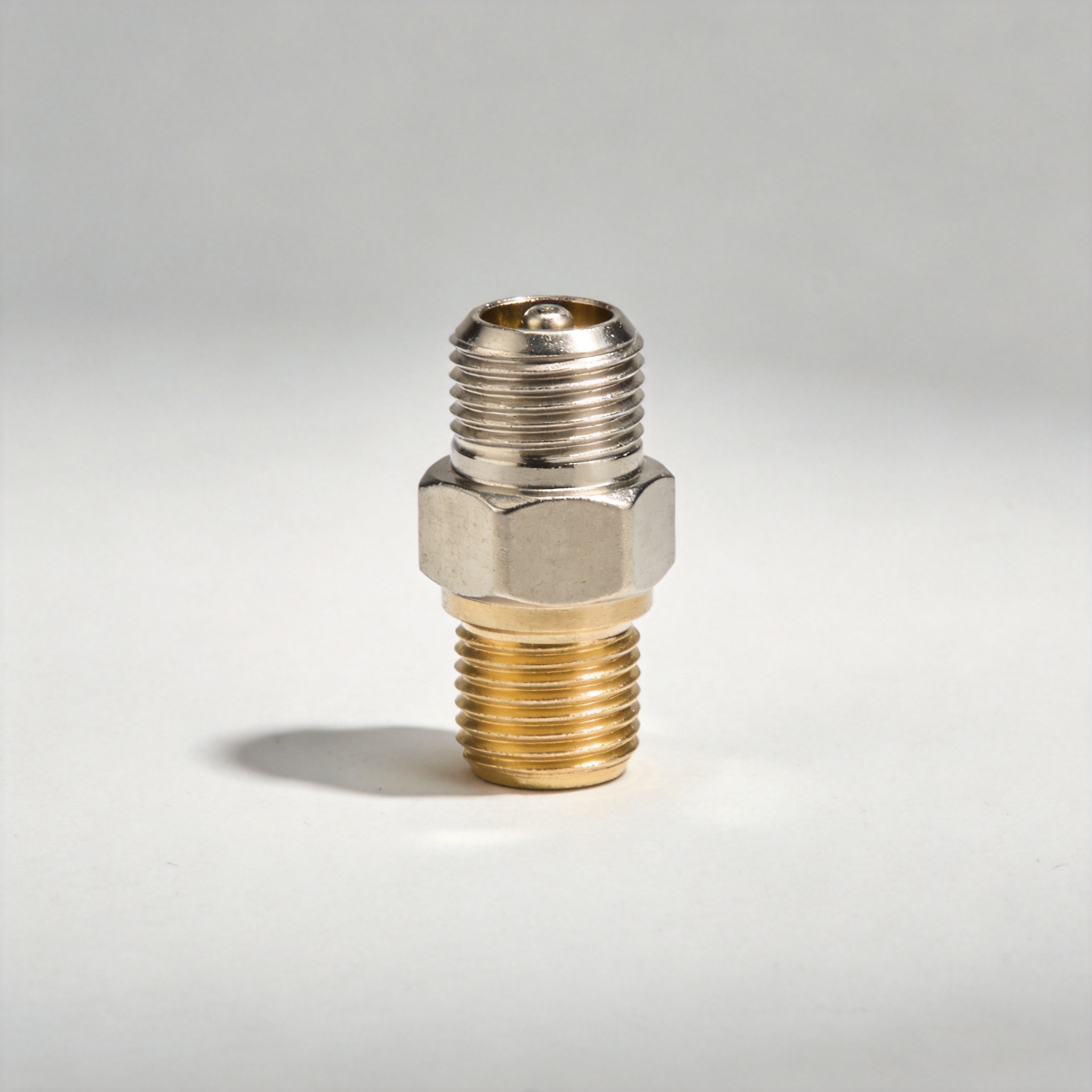
In mission-critical radio frequency (RF) designs, choosing the right physical interconnect determines signal integrity, environmental endurance, and system uptime. While general-purpose RF interfaces look similar on paper, their mechanical coupling, grounding geometry, and frequency response vary significantly under real-world stress.
This guide provides a focused, technical breakdown comparing the n type antenna connector against alternative interfaces like BNC and TNC. We examine impedance stability, power handling, vibration limits, and protective inline components—such as the dc block n type module—to simplify your engineering and procurement decisions.
Electrical & Mechanical Parameter Comparison
Selecting an RF interface requires balancing operating frequency, power threshold, and mechanical stability. The n type antenna connector features a 5/8-24 threaded coupling mechanism that maintains uniform 360-degree ground contact pressure, significantly reducing passive intermodulation (PIM) and maintaining low Voltage Standing Wave Ratio (VSWR).
| Parameter | Standard N-Type Connector | BNC Connector | TNC Connector |
| Coupling Mechanism | Threaded (5/8-24 pitch) | Quick-turn Bayonet | Threaded (7/16-28 pitch) |
| Impedance | 50 Ω (75 Ω specialized) | 50 Ω / 75 Ω | 50 Ω / 75 Ω |
| Frequency Range | DC to 11 GHz (Precision air: 18 GHz) | DC to 4 GHz | DC to 11 GHz |
| Vibration / Strain | High (Bulkhead & Heavy Feeder Duty) | Low (Benchtop & Laboratory Duty) | Medium (Panel & Mobile Duty) |
| Ingress Protection | IP67/IP68 with Internal O-Rings | Non-sealed (Requires tape/boots) | Partial (Requires external booting) |
| Standard Norms | MIL-STD-348 / MIL-PRF-39012 | MIL-STD-348 | MIL-STD-348 |
When high RF power or weatherproofing is required, the medium-sized n type antenna connector outperforms bayonet-style alternatives like the BNC, which suffer from contact instability under heavy cable pull.
PIM Mitigation & Vibration Stability in Public Safety Networks
First responders, municipal emergency services, and smart-grid operators rely on Land Mobile Radio (LMR), VHF, and UHF bands where signal loss or intermittent connectivity is unacceptable. In these environments, deploying a rugged vhf antenna connector setup on vehicle bulkheads or remote terminal units (RTUs) requires mechanical resistance to constant shock and thermal cycling.
Critical RF Signal & Isolation Path Topology:
[VHF Transceiver (RF Source Unit)] ---> [DC Block N Type (Protects DC)] ---> [N-Female Panel (Bulkhead Interface)] ---> [N-Male Coax (Antenna Feeder)]
Signal Flow Architecture
-
Transceiver Output: The primary LMR transceiver generates high-power RF signals.
-
Inline Protection: An inline dc block n type coaxial module is installed directly at the cabinet front panel. This component isolates DC bias voltages up to 100V while passing RF signals with less than 0.15 dB insertion loss.
-
Bulkhead Transition: The signal flows through a panel-mounted female n type antenna connector anchored to the cabinet chassis, transferring mechanical stress away from internal circuit boards.
-
Feeder Line: A ruggedized corrugated coax assembly terminated with a male vhf antenna connector routes the signal up the tower or mast.
Unlike BNC connectors—which can disconnect or create microphonic noise under vibration—the threaded n type antenna connector maintains constant torque, protecting critical VHF link quality.
High-Voltage DC Isolation & Front-End Protection
In modern cellular small cells, outdoor Wi-Fi gateways, and RF test setups, active electronics often inject DC bias onto the transmission line to power tower-mounted amplifiers (TMAs). Without isolation, these DC offsets can damage sensitive spectrum analyzer inputs, receivers, or baseband units (BBUs).
Inline DC Block N Type Internal Isolation Mechanism:
-
Input Side (RF + DC Input / Active Line): Passes combined RF signals and DC power feeds.
-
Core Blocking Component: Precision Center Capacitor isolates up to 50V–100V DC offset voltages.
-
Outer Shield Pass: Outer conductor maintains continuous ground potential and RF shielding.
-
Output Side (Pure RF Output): Delivers isolated RF signals directly to sensitive receivers or Vector Network Analyzers (VNAs).
Integrating an inline dc block n type unit inserts a precision inner-conductor capacitor into the signal path. This design blocks direct current and low-frequency ground loops while allowing high-frequency RF signals to pass cleanly from DC-cut frequencies up to 18 GHz.
Whether configured on an industrial IoT gateway chassis or a laboratory calibration bench, combining an inline dc block n type protector with a panel-mounted female n type antenna connector safeguards sensitive equipment from power surges and ground potential differences.
Engineering Procurement & Field Installation Checklist
To ensure long-term reliability in outdoor infrastructure and high-frequency test environments, evaluate these primary selection criteria:
-
Frequency & VSWR Verification: Confirm that the n type antenna connector assembly maintains a VSWR below 1.15:1 across your operational frequency range (e.g., LMR 150–470 MHz, Cellular 600 MHz–6 GHz, or C-band).
-
Ingress Protection & Sealing: Ensure the connector housing features internal silicone O-rings compliant with IP67 or IP68 standards. For permanent outdoor installations, pair the vhf antenna connector entry point with cold-shrink boots.
-
DC Bias Safeguards: Check if your system architecture includes active power injection. If so, place a dc block n type component upstream of delicate receiver electronics.
-
Cable Strain Relief: Select precise crimp or clamp dimensions matching your specific coax cable (e.g., LMR-400, RG-213, or 1/2-inch superflexible corrugated cable) to prevent braid displacement and moisture ingress.
-
Standard Compliance: Verify that all components meet international defense and commercial specifications, including MIL-PRF-39012, MIL-STD-348, and IEC 61169-16.
Summary & Custom Assembly Sourcing
Choosing between N-Type, BNC, and TNC connectors comes down to your frequency range, environmental exposure, and mechanical stress requirements. For high-power outdoor telecommunications, public safety radio systems, and precision lab environments, the n type antenna connector remains the industry standard for durability and low-loss performance.
For detailed technical datasheets, PIM-tested cable assemblies, and certified interconnect hardware tailored to your system architecture, visit





