 EN

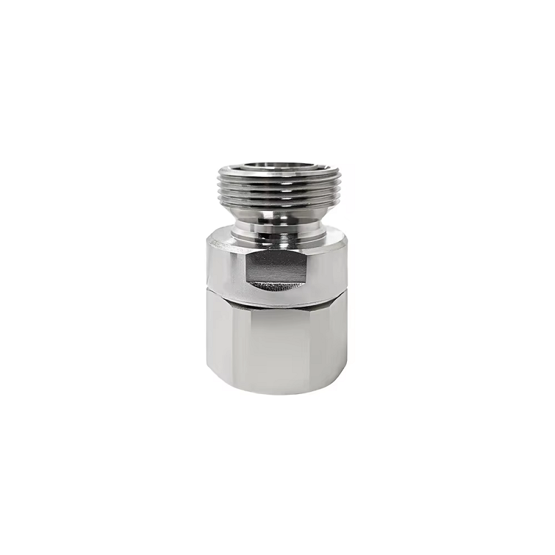
Sourcing 7 16 Din Connector from Reliable OEM Manufacturers
For an OEM buyer, selecting a 7 16 din connector is less about finding a familiar interface name and more about proving that the mated connector, cable, installation method, and test plan will work together. I approach this as a telecom-infrastructure procurement review: define the RF duty first, then check interface compatibility, environmental exposure, assembly controls, and supplier evidence. That sequence prevents a low unit price from becoming a field-rework cost.
Where a 7 16 din connector fits
A 7 16 din connector is a threaded RF coaxial interface commonly specified for high-power, low-intermodulation antenna and feeder connections. It is most at home in cellular base stations, broadcast sites, distributed antenna systems, and outdoor RF infrastructure. IEC 61169-4 is the relevant interface standard family for 50-ohm type 7-16 connectors; it is a useful starting point, but it does not replace reviewing the exact supplier drawing and qualification data.
Telecom is not the only application. Security integrators may use robust RF links around perimeter or transport systems, while industrial automation teams can encounter high-reliability RF interconnects in private wireless, remote sensing, and test installations. In every case, the RF chain must have a consistent impedance. Do not assume that a connector with a similar physical appearance can be mixed freely with a 75-ohm assembly, a 7 8 coax feeder, or an adapter without checking the complete design.
Start with four buying questions
- What is the system impedance and frequency band? Confirm the whole path, including antenna, cable, adapters, and instruments. A 50-ohm 7 16 din connector is often the expected choice for high-power cellular feeder paths, but the purchase specification must state the required operating band and acceptable return-loss or VSWR criteria.
- What cable is actually being terminated? The cable diameter, corrugation, braid construction, dielectric, and preparation method determine the compatible termination. A 7 8 coax feeder needs a connector kit explicitly designed for that cable construction. An rg8 connector requirement is a different cable-family question, not a shorthand substitute for the large feeder interface.
- What will the installation see? Record indoor or outdoor use, UV exposure, salt spray, vibration, temperature cycling, and water exposure. Ask whether the stated ingress rating applies when mated, with the specified gasket, boot, and tightening process—not to an unmated component on a catalog page.
- What must be demonstrated at acceptance? Set expectations for visual inspection, torque control, continuity, insulation condition, VSWR or return loss, insertion loss where applicable, and PIM testing when the network design requires it.
Compare 7/16 DIN with SMA, N, BNC, and TNC correctly
| Interface | Best-fit decision context | What an OEM buyer should verify |
|---|---|---|
| 7/16 DIN | High-power outdoor feeder and antenna connections where rugged threaded mating and low-PIM control matter. | 50-ohm requirement, cable-specific termination, mating torque, weather sealing, PIM evidence, and service access. |
| SMA | Compact equipment, test, and higher-frequency interconnects where space is constrained. | Frequency range, gender and mating geometry, torque discipline, and whether the smaller interface suits the power and environmental duty. |
| N | General-purpose RF equipment and outdoor links where a threaded medium-size interface is suitable. | Impedance variant, frequency capability, environmental configuration, and adapter stack-up. |
| BNC | Quick-connect laboratory, video, instrumentation, or lower-duty RF connections. | Whether bayonet retention, vibration exposure, and impedance variant are appropriate for the system. |
| TNC | Threaded connections needing better vibration resistance than a bayonet interface in compact RF equipment. | Thread engagement, impedance, environmental sealing, and mating-cycle requirements. |
The comparison is not a performance ranking. It is an interface-fit check. For example, specifying SMA because it supports a desired frequency does not make it a replacement for a 7 16 din connector in a high-power outdoor feeder. Likewise, a small umcc connector is intended for compact internal RF board-to-cable work and should be assessed in that context rather than compared as a field-replaceable tower interface.
Turn a catalog listing into an OEM-ready specification
Ask suppliers to quote against a controlled data sheet rather than an informal description. Include connector gender and orientation, system impedance, operating frequency, cable make and size, attachment method, body and contact materials, plating, environmental target, mating-cycle expectation, and any PIM, return-loss, insertion-loss, or power-handling acceptance values. Specify the standards or customer documents that govern the part and identify which values are design targets versus lot-acceptance requirements.
For reference, this cataloged RF-DIN-75A DIN 7/16 Connector is described as a 75-ohm, 6 GHz, IP67 product. Treat that as a distinct interface option that needs system-level impedance confirmation; it should not be assumed interchangeable with a 50-ohm feeder design. Where a mixed-interface arrangement is required, the RFX-Custom-02 high-power RF connector is a supplier-listed 7/16 DIN female to N male configuration whose stated frequency and power details must be checked against the intended operating condition.
Installation controls that protect RF performance
Even a qualified 7 16 din connector can underperform after poor assembly. Use the cable manufacturer’s stripping dimensions and tooling, keep conductive debris out of the dielectric area, and inspect center-contact seating before mating. Start threads by hand to avoid cross-threading; then use the torque range specified for the exact connector and cable assembly. Published examples show approximately 25 N-m as a minimum working mating torque for some 7-16 designs, but it is not a universal field instruction.
For outdoor work, inspect seals before closure, route the feeder to avoid connector-side bending loads, and follow the approved weatherproofing sequence. A wrap that hides an incorrectly mated interface does not create an ingress rating. Record lot numbers, installation location, torque verification, and test results so a later fault investigation can distinguish a component issue from an assembly issue.
Build a practical incoming and final-test plan
Before volume release, request samples that represent the real cable and configuration. Check thread action, coupling-nut condition, plating consistency, marking, and packaging. For the electrical plan, agree on the frequency sweep, calibration method, test ports, pass/fail limits, and report format. For low-PIM networks, document test power, tones, fixture condition, and cable routing because the measurement is sensitive to the entire setup.
A reliable OEM partner should be able to clarify open specification points before production and provide relevant test evidence for the supplied assembly. That is more useful than a generic claim of compatibility. If your system also uses N interfaces, compare the supplier-listed RF-N-75B low-PIM N connector as its own 75-ohm option rather than treating it as a direct substitute for a 50-ohm 7/16 feeder connection.
Supplier qualification checklist
- Match the connector and cable part numbers to the approved drawing and system impedance.
- Request material, plating, environmental, and electrical specifications for the exact configuration.
- Confirm the supplier’s controlled assembly instructions, tooling, and inspection checkpoints.
- Review sample test data before approving a production lot, especially for return loss and PIM-critical links.
- Define traceability, packaging protection, labeling, change control, and nonconformance handling in the purchase order.
- Use a pilot installation to confirm access, torque practice, weatherproofing, and field-test workflow before broad deployment.
Choose evidence, not just an interface
The right 7 16 din connector is the one that fits the RF design and can be installed, verified, and traced consistently at scale. Start with impedance and cable compatibility, use interface comparisons to avoid category mistakes, and insist on the product-specific documents that support your environmental and electrical requirements. With that discipline, telecom, security, and industrial automation buyers can source a connection that is not merely compatible on paper, but controllable through installation and acceptance.





