 EN

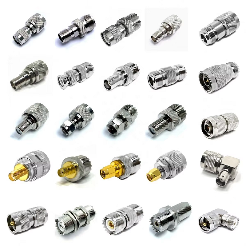
In defense communications, security enclosures, and high-reliability industrial automation, severe enclosure constraints frequently force a 90-degree turn in the coaxial signal path. A right angle sma connector provides a space-saving solution where rack depth, chassis clearance, or tight cable routing bends prevent the use of straight coaxial connectors. However, making a 90-degree physical turn must not introduce uncontrolled impedance mismatches, high reflection loss, or premature mechanical failure under mechanical shock and vibration.
Specifying a right angle sma connector requires an engineering approach that evaluates the complete 50-ohm signal path. This includes matching the exact sma right angle geometry to cable construction, defining frequency caps up to 18 GHz, establishing weatherproofing limits, and enforcing rigorous Vector Network Analyzer (VNA) sweep inspection criteria.
Phase 1: RF Path Optimization & Frequency Boundaries
An sma right angle design introduces an internal right-angle bend in the center pin and dielectric structure. In low-cost commercial connectors, this internal junction can create a sharp inductive spike or impedance discontinuity. For precision military and industrial equipment, a premium right angle sma connector features a swept or precision-mitered internal conductor transition that preserves a smooth 50-ohm characteristic impedance across its entire operating bandwidth.
When specifying a right angle sma connector, do not rely on generic "SMA" label designations. Standard commercial SMA interfaces may degrade rapidly above 6 GHz or 12.4 GHz due to dielectric tolerances. High-frequency applications require fully verified 18 GHz components—such as gold-plated brass or passivated stainless steel variants—with documented VSWR ratings (typically < 1.25:1 at 18 GHz).
Phase 2: Cable Integration & Interface Matching
Selecting the correct right angle sma connector depends heavily on the physical coaxial cable line. Termination methods, strain relief designs, and outer jacket support differ substantially across cable families.
| Selection Metric | Miniature Flexible Cable | High-Power Low-Loss Feeder | Rugged Industrial Interface |
| Primary Cable / Interface | rg316 sma connector build | lmr 400 sma connector transition | right angle sma connector to N/TNC |
| Cable Outer Diameter | ~2.5 mm (0.100 in.) | ~10.3 mm (0.405 in.) | Varies by interface style |
| Key Mechanical Factor | Internal crimp sleeve & strain boot | Mechanical leverage & strain relief | Thread coupling / Bayonet torque |
| Typical Frequency Cap | DC to 3 GHz / 6 GHz | DC to 6 GHz | DC to 11 GHz / 18 GHz |
| Environmental Target | Internal chassis, IP50 | Outdoor cabinets, IP67 / IP68 | Military field gear, MIL-STD-202 |
Miniature Cable Runs: RG316 Assemblies
Deploying an rg316 sma connector assembly is ideal for compact internal equipment bays, airborne telemetry units, and dense PCB routing. Because RG316 features a stranded silver-plated copper-clad steel center conductor and PTFE dielectric, an rg316 sma connector must utilize precision crimp or solder ferrules. The sma right angle body must capture the outer braid securely to prevent contact pull-out when routed through tight, moving mechanical assemblies.
Heavy-Duty Cable Transitions: LMR 400 Lines
Integrating an lmr 400 sma connector configuration introduces unique mechanical challenges. LMR 400 is a thick (~10.3 mm), low-loss cable with a solid conductor and stiff PE jacket. While a compact lmr 400 sma connector reduces back-panel depth inside outdoor control boxes, the heavy cable exerts significant mechanical leverage on the SMA interface. To prevent thread stripping or panel deflection, installers must secure the LMR 400 cable with rigid external support clamps within 100 mm of the sma right angle housing.
Phase 3: Comparing RF Interfaces for Severe Operating Environments
When designing multi-band industrial gear or military communications, choosing between an SMA, N-Type, BNC, or TNC interface depends on power handling, mechanical vibration, and field service requirements:
-
SMA Interface: Compact 50-ohm threaded coupling ideal for space-constrained chassis and test setups up to 18 GHz. Requires precise torque control (typically 7–10 in-lbs) to avoid damaging gold-plated mating faces.
-
N-Type Interface: Robust, larger threaded connector engineered for high-power outdoor infrastructure and macro base stations. Lower frequency cap (~11 GHz or 18 GHz precision grade) but superior physical durability and weather sealing.
-
TNC Interface: A threaded version of the BNC connector offering strong resistance to high vibration and mechanical shock. Excellent for military vehicle communications where bayonet connectors might unlock.
-
BNC Interface: Quick-connect bayonet coupling designed for rapid maintenance and low-frequency instrument connections (< 4 GHz). Not recommended for high-vibration military environments due to contact chatter.
Phase 4: Procurement Specifications & Quality Verification Steps
To ensure predictable factory yields and reliable incoming inspection, procurement teams should build explicit requirements into every drawing and purchase order:
-
Complete Specification Callout: Clearly state the nominal impedance (50 Ohm), verified frequency band (e.g., DC–18 GHz), cable model, plating (e.g., 30 u-in. gold over nickel), and housing material (passivated SS304 or gold-plated brass).
-
Ingress Protection (IP Rating): Specify exact sealing levels (e.g., IP67 or IP68 submerged) in both mated and unmated conditions, including internal O-rings and silicone gaskets.
-
Acceptance Test Records: Require 100% factory screening for DC continuity and pin insulation resistance, along with lot-sampled Vector Network Analyzer (VNA) sweep records for insertion loss and VSWR across the operating band.
Sourcing managers looking for verified custom assemblies can reference suppliers like
Step-by-Step Installation & Quality Control Sequence
Examine the center pin, internal dielectric, and precision threads of the right angle sma connector. Verify that no metallic burrs, dirt, or plating flakes are present on the mating interface.
Shape the coaxial cable line (especially when using an lmr 400 sma connector or rigid jumper) so the sma right angle body sits naturally against the mating bulkhead port without forcing or twisting.
Hand-thread the coupling nut to prevent cross-threading. Finish tightening using an calibrated RF torque wrench set to 8 in-lbs (0.9 Nm) for brass SMA bodies or 10 in-lbs for stainless steel variants.
Connect the completed assembly to a Vector Network Analyzer. Measure return loss and insertion loss across the entire operating band, verifying that the right angle sma connector transition meets your system's link budget criteria.





