 EN

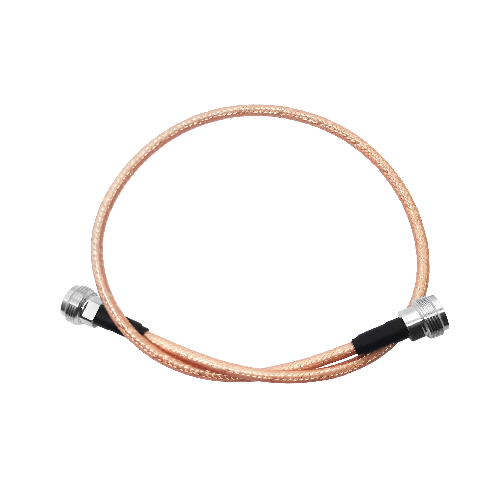
Testing and Verifying Bnc Coaxial Cable Assembly Signal
A bnc coaxial cable assembly can look correct at the bench and still compromise a link after installation. The connector may mate cleanly, the cable jacket may be intact, and continuity may pass, yet an impedance step, a damaged braid, or an over-tight bend can add reflections that only appear under the intended frequency and load. A reliable acceptance process therefore checks the finished assembly as a transmission path, not as a collection of separate parts.
For purchasing and field teams, the useful question is not simply “does it pass continuity?” Ask instead: does this bnc coaxial cable assembly preserve the impedance, shielding, and loss budget required by the equipment at both ends? That change in viewpoint makes cable selection and verification much more predictable.
Start with the coaxial structure
Every bnc coaxial cable assembly has four working layers: a center conductor, dielectric, shield, and outer jacket. The conductor carries the signal; the dielectric holds the conductor in position; the shield provides a controlled return path and limits unwanted coupling; and the jacket protects the structure during routing and service. Their dimensions and materials jointly set characteristic impedance. A kinked dielectric or an uneven connector termination is not merely cosmetic—it can create a localized impedance discontinuity.
Shield coverage matters most where the installation is electrically noisy or mechanically active. A single braid, dual shield, or foil-plus-braid construction should be selected against the actual exposure: nearby drives, radio equipment, transmitters, cable trays, vibration, moisture, and repeated movement. Inspect the termination closely. Loose braid strands, an incomplete crimp, or a poorly prepared shield-to-connector contact can weaken both screening and return-loss performance.
Know what the key electrical tests reveal
Continuity and insulation resistance are sensible first screens, but they do not verify RF behavior. For a bnc coaxial cable assembly, use the test that matches the system risk:
- Continuity and short test: confirm the center path is continuous and isolated from the outer conductor.
- Insertion loss: measure the reduction in transmitted signal through the completed assembly at the frequencies that matter. Total assembly loss includes cable loss, connector loss, and mismatch loss.
- Return loss or VSWR: look for reflections caused by impedance changes. Better return loss generally means less reflected energy; compare the result with the equipment and project acceptance criteria rather than using one universal value.
- Shield and mechanical inspection: examine the jacket, braid termination, strain relief, connector retention, and the entire routed length.
A sweep measurement is especially valuable when the run is long, the operating frequency is high, or the system has little link-margin reserve. If the result is unexpectedly poor, isolate the cable from the connectors where practical. The correction is often not “replace the cable.” It may be a damaged termination, a sharp route behind a panel, or an impedance mismatch at an adapter.
50 ohm and 75 ohm: select the system impedance first
Impedance is a system requirement, not a label to mix casually. A 50-ohm bnc coaxial cable assembly is commonly used in RF, instrumentation, antenna, and test applications. A 75-ohm assembly is commonly used in video and other systems designed around 75-ohm transmission paths. The cable, connector interface, source, load, and any adapters should be reviewed as one chain.
| Selection question | 50-ohm path | 75-ohm path |
|---|---|---|
| Typical context | RF equipment, antennas, laboratory and communications links | Video-oriented and 75-ohm distribution links |
| Verification focus | Frequency-range loss, return loss/VSWR, connector condition | Impedance continuity, video-path loss and reflection control |
| Procurement control | Confirm every component is specified for the 50-ohm system | Confirm cable and BNC interface are intended for the 75-ohm system |
Do not rely on appearance alone to identify the correct BNC configuration. Confirm the product specification and the equipment documentation. If an adapter is unavoidable, include it in the end-to-end verification rather than treating it as electrically invisible.
Compare cable families by installation constraints
bnc rg58 is often considered when a flexible 50-ohm cable is needed for short interconnects, mobile equipment, or tight indoor routing. Its flexibility can simplify installation, but attenuation rises with frequency and length, so verify the loss budget rather than assuming a familiar cable designation will fit every run.
bnc rg59 is associated with 75-ohm applications and should be evaluated as part of a consistent 75-ohm path. It is not a substitute for a 50-ohm RF assembly simply because the connectors can appear compatible. The same caution applies when a legacy drawing specifies a BNC endpoint without stating the system impedance.
For a long 50-ohm run where lower attenuation is a priority, consider the project’s routing and installation conditions alongside cable loss. The verified product catalogue includes LMR400 Low-Loss 50 Ohm Coaxial Cable; evaluate its published specifications and minimum-bend requirements against the route before committing. The catalogue also includes a Worldpeak SS402 Pre-Terminated Cable Assembly and a Worldpeak RG196 50-Ohm Coaxial Cable: Engineering Data & Selection Guide. Use the confirmed product pages to compare the applicable assembly format and published data; do not infer interchangeability from the product names.
Installation checks that prevent avoidable signal loss
Before pulling the route, establish the cable manufacturer’s stated minimum bend radius and keep a margin where repeated flexing, temperature changes, or vibration are expected. A bend that seems acceptable during installation can deform the dielectric or fatigue the shield over time. Avoid cable ties so tight that they flatten the jacket, and provide strain relief so connector torque is not carried by the center contact.
- Record the intended impedance, frequency range, maximum assembly length, and connector gender before purchasing.
- Inspect the received bnc coaxial cable assembly for labeling, connector condition, jacket damage, and specified length.
- Check continuity and isolation before routing; then repeat after routing to catch installation damage.
- Perform insertion-loss and return-loss or VSWR verification at the operating band when the system is RF-sensitive or the run is mission-critical.
- Document the test setup, frequency range, adapters used, and acceptance limits so future troubleshooting has a baseline.
Where does RJ45 to BNC fit?
An rj45 to bnc item is an interface transition, not a direct proof that Ethernet signaling and coaxial RF requirements are interchangeable. Check what the equipment actually expects: a balun, video interface, protocol converter, or a physical connector adapter may each serve a different purpose. Verify impedance, signal format, bandwidth, and power requirements before adding the transition to a bnc coaxial cable assembly path.
Final acceptance rule
Choose the assembly by the whole link: impedance, frequency, loss budget, shielding exposure, connector style, route, and bend radius. Then test the completed path after installation. That method gives buyers a clearer basis for comparing bnc rg58, bnc rg59, and lower-loss alternatives, while giving installers a repeatable way to find signal problems before the system goes live.





