 EN

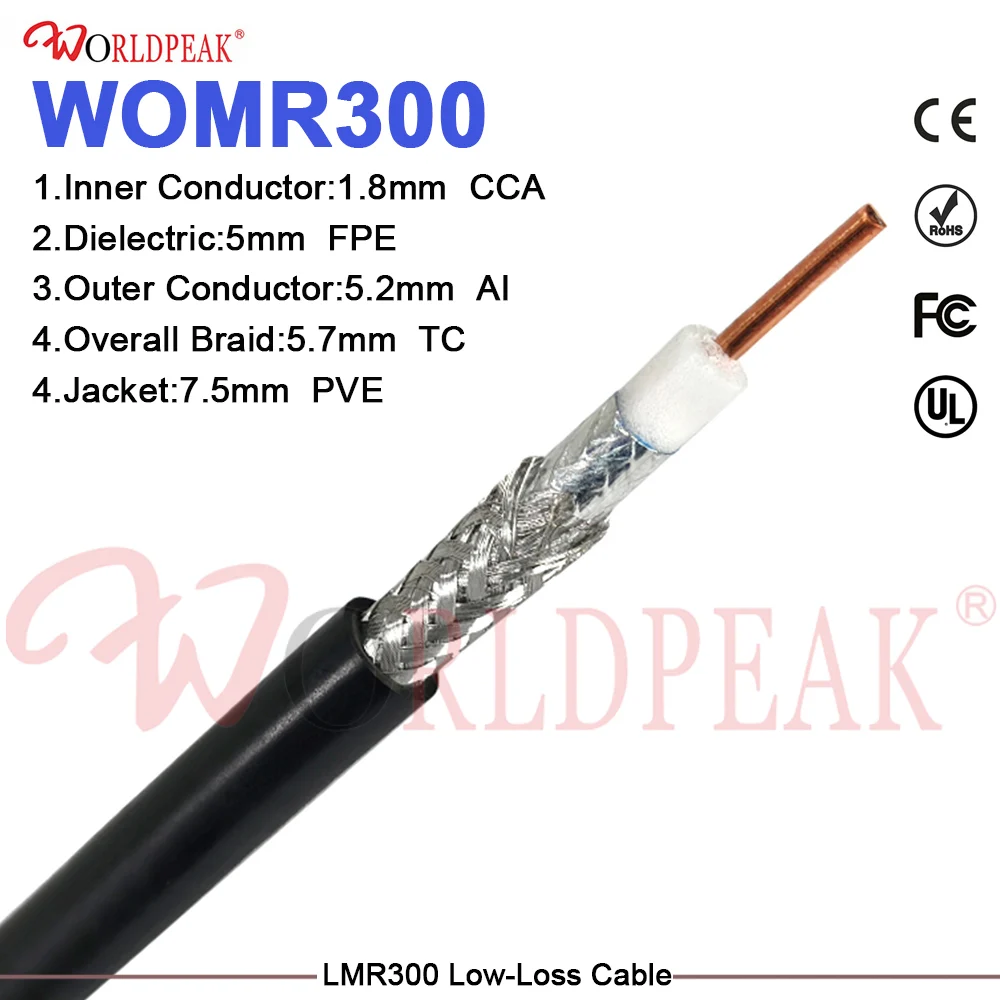
In modern telecommunications, broadcasting, and industrial wireless infrastructures, the physical link between transmitters, receivers, and antenna arrays forms the backbone of reliable connectivity. A core element of this transmission path is the communication feeder cable. Whether deployed in cellular base stations, maritime communication arrays, or high-capacity data networks, maintaining signal integrity over long transmission distances is vital. Over time, environmental exposure, mechanical stress, and installation flaws can degrade performance, making rigorous feeder cable signal testing an indispensable engineering practice.
As a specialized global manufacturer,
Core Electrical Metrics in Feeder Cable Signal Testing
When evaluating a communication feeder cable, engineers look beyond simple continuity checks. High-frequency signal transmission involves complex wave propagation dynamics where minor physical imperfections translate into massive signal reflections. Effective feeder cable signal testing focuses on three primary parameters:
-
Return Loss and VSWR: Return loss measures the power reflected from the load or an impedance mismatch back toward the source. In a high-quality communication feeder cable, return loss values should remain high (typically greater than 20 dB, corresponding to a Voltage Standing Wave Ratio of less than 1.22:1). High VSWR indicates structural damage, pinching, or water ingress along the run.
-
Insertion Loss and Attenuation: Attenuation measures how much signal power is lost as electromagnetic waves travel down the communication feeder cable. High-frequency signals suffer higher attenuation per unit length. Testing helps confirm that insertion loss matches theoretical manufacturer specifications across specific frequency bands.
-
Characteristic Impedance Uniformity: Most professional RF networks rely on a strict 50 Ohm impedance standard. Localized variations in braid density or dielectric thickness can cause impedance bumps, generating internal reflections that degrade data throughput.
Advanced Testing Methodologies and Diagnostic Equipment
Detecting faults hidden beneath the outer jacket of a communication feeder cable requires specialized diagnostic tools. Relying solely on basic multimeters is insufficient for high-frequency RF verification.
-
Time Domain Reflectometry (TDR): TDR instruments send a fast-rise electrical pulse down the communication feeder cable and analyze the reflected waveform. By calculating the time delay and magnitude of reflections, technicians can pinpoint the exact physical location of a kink, connector mismatch, or moisture pocket within centimeters.
-
Frequency Domain Reflectometry (FDR) and Swept Tests: FDR provides superior sensitivity for distributed faults compared to traditional TDR. By sweeping across an operational frequency range, technicians uncover subtle periodic impedance variations that only manifest under live high-frequency loads during active feeder cable signal testing.
-
High-Power CW (Continuous Wave) Intermodulation Testing: Passive Intermodulation (PIM) testing is crucial for multi-carrier cellular systems. Hidden micro-discontinuities or oxidized contacts in the communication feeder cable assembly can generate spurious signals, desensitizing base station receivers.
Parameter Comparison: Field Diagnostic Tools vs. Factory Bench Analyzers
To understand the difference between routine maintenance checks and rigorous production testing, the following table compares field verification methods with factory-grade analysis for any communication feeder cable.
| Evaluation Parameter | Field Maintenance Testing | Factory Bench Analysis (Worldpeak QC) |
| Primary Test Equipment | Handheld Cable and Antenna Analyzer | Vector Network Analyzer (VNA) & Swept PIM Test Benches |
| Frequency Sweep Range | Operational band (e.g., 700 MHz to 2.7 GHz) | Ultra-wideband (DC to 6.0 GHz+) |
| Fault Location Precision | Within 0.5 meters via TDR | Sub-millimeter dielectric integrity inspection |
| Environmental Stress | Ambient field conditions | Controlled thermal and salt-fog chambers |
| Documentation Output | Pass/Fail summary logs with trace files | Full compliance and traceability datasets |
Engineering Pitfalls and Real-World Signal Verification Case Study
Even the most robust communication feeder cable can fail prematurely if installation and verification protocols are compromised by common engineering oversights.
Common Engineering Pitfalls
-
Exceeding Minimum Bend Radius: Forcing a heavy-gauge communication feeder cable around tight corners collapses the internal dielectric foam, permanently altering impedance and causing high-frequency signal reflection spikes.
-
Improper Sealing and Weatherproofing: Moisture ingress is the silent killer of outdoor RF lines. Water absorption drastically increases dielectric loss, rendering standard feeder cable signal testing results unstable over diurnal temperature shifts.
Real-World Telemetry Case Study
A regional cellular operator experienced unexplained uplink degradation across several remote tower sites. Initial visual inspections of the external communication feeder cable runs revealed no outer jacket damage. However, a comprehensive sweep using frequency domain reflectometry during routine feeder cable signal testing uncovered a severe impedance anomaly 12 meters below the top connector, caused by an over-tightened hoisting grip that pinched the internal copper conductor. Replacing the damaged section and enforcing strict installation torque guidelines restored optimal signal throughput and eliminated dropped calls.
Worldpeak Manufacturing and Quality Assurance Standards
Achieving reliable long-term performance in any communication feeder cable starts on the factory floor. At
-
Continuous Dielectric Monitoring: Laser micrometer systems monitor foam polyethylene insulation dimensions in real-time during extrusion, ensuring uniform electrical performance along every meter of the communication feeder cable.
-
100% Swept Frequency Inspection: Every production spool undergoes automated sweep testing to verify return loss and attenuation parameters prior to packaging.
-
Material Traceability and Compliance: Our manufacturing protocols adhere to rigorous international environmental and mechanical standards, ensuring that every communication feeder cable delivers exceptional durability in harsh outdoor environments.
By combining precision manufacturing with systematic feeder cable signal testing, network operators can ensure uninterrupted, high-frequency connectivity. Explore our comprehensive engineering framework and full product lineup on our





