 EN

Testing and Verifying Type N Female Connector Signal
A type n female connector can look correct at the enclosure wall or cable end and still introduce a measurable signal problem. In telecom, security, and industrial-automation RF paths, the connector is part of the transmission line—not merely a mechanical join. The practical question is therefore not only whether an N male mates with the interface, but whether the completed path holds its impedance, remains protected from the environment, and meets the measurement requirement at the operating band.
From a field-installation perspective, the reliable sequence is simple: specify the interface before ordering, inspect the termination before mating, protect the finished joint, then verify the assembled signal path. That sequence is especially useful when an antenna feeder, a camera backhaul, or a factory wireless link contains adapters and panel transitions that are easy to overlook.
Start With the Electrical Interface, Not the Thread
Type N is a threaded, medium-size RF interface often chosen where coupling security and outdoor durability matter. But a threaded coupling alone does not establish electrical compatibility. Confirm the system impedance, connector gender, cable construction, operating-frequency range, and mounting style before treating two parts as a pair. A 50 Ω system should be built from 50 Ω components unless the RF design explicitly calls for another impedance. Published N-series information also distinguishes 50 Ω and 75 Ω versions; physical-looking similarity is not a reason to mate them.
For a type n female connector, document whether it is a cable termination, bulkhead/panel mount, chassis mount, or adapter side. Then verify the mating half and any intermediate adapter. The terms sma male to n female, n male to sma female, and n male sma female are not interchangeable shopping shorthand: each must describe the exact gender and interface on both ends, plus the required impedance and frequency capability.
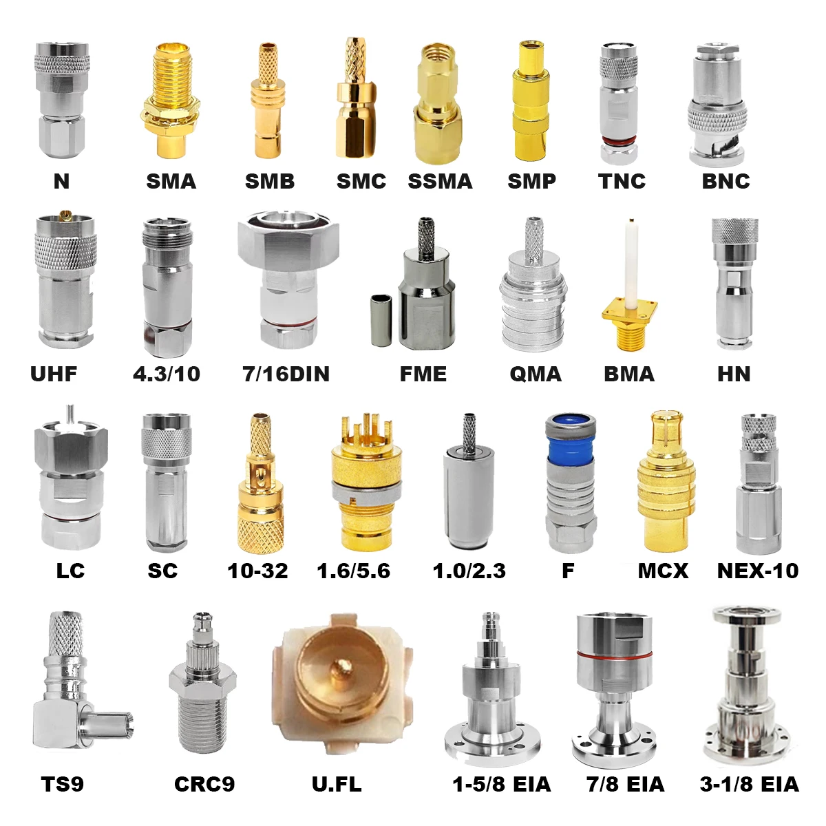
Where N, SMA, BNC, and TNC Fit
| Interface | Useful context | Verification priority |
|---|---|---|
| N | Threaded coupling and a robust form factor suit many outdoor feeder, antenna, and infrastructure connections. | Impedance, weather sealing, torque, and cable support. |
| SMA | Compact interface commonly used in dense equipment and higher-frequency RF assemblies. | Thread condition, torque discipline, adapter quality, and frequency headroom. |
| BNC | Quick-connect interface often selected where frequent handling is more important than a threaded coupling. | Correct impedance version and secure bayonet engagement. |
| TNC | Threaded alternative often considered where vibration resistance is valuable. | Interface specification, mating condition, and environmental protection. |
No connector family is universally suitable. Choose the interface that fits the installed system rather than trying to solve a space, weather, or frequency constraint with a generic gender changer. The same principle applies to an sma male to n female adapter: it may be appropriate for a defined transition, but it adds another interface that should be included in the verification plan.
Inspect Before You Mate
Before connecting a type n female connector, check that the center contact is centered and undamaged, the dielectric is clean and not recessed, and the external thread starts smoothly. On cable assemblies, inspect the strain-relief area, braid capture, and jacket cutback for signs of an uneven termination. A connector can pass a visual glance yet have a distorted contact or poorly prepared shield that changes the RF behavior under flexing.
- Match the connector design to the actual cable diameter and construction; do not force a termination intended for a different cable family.
- Use clean, compatible mating faces. Loose metal fragments, moisture, or damaged plating can raise contact resistance and reflection.
- Use the connector manufacturer’s torque recommendation and an appropriate torque tool where the installation procedure requires it. Over-tightening can damage threads or dielectric parts; under-tightening can leave an unstable RF interface.
- Support the cable so that connector weight, vibration, and bend forces are not transferred into the mating plane.
Protect the Installed Connection
Indoor cabinet interfaces and exposed antenna-side interfaces need different protection plans. In an outdoor telecom or security deployment, water can enter through a poorly sealed connector-to-cable transition or through a damaged wrap. Select the enclosure and sealing method for the actual exposure, preserve cable bend radius, and inspect the joint after routing. In a vibration-prone industrial setting, add strain relief and make mechanical inspection part of routine maintenance.
This is where system-level thinking matters. A component may be appropriate on a specification sheet, yet performance can drift after repeated handling, a tight cable bend, or seasonal moisture exposure. For qualification-sensitive builds, request the applicable environmental, electrical, and traceability documentation rather than assuming a product title proves suitability.
Verify Signal Performance After Installation
Visual inspection comes first, but it is not the final test. A vector network analyzer (VNA) can measure return loss, VSWR, and insertion loss across the intended band. VSWR close to 1 indicates a closer impedance match; return loss expresses reflection in dB. The acceptance criterion should come from the system specification, cable length, number of interfaces, and operating frequency—not from a generic number copied from another project.
- Define the test plane. Decide whether the measurement covers one type n female connector, an adapter pair, or the complete cable-and-connector assembly.
- Calibrate for the connectors used. Use a suitable calibration method and verify the instrument setup before judging the installed path.
- Sweep the working band. Check the frequencies the system will actually use, including any specified margin where appropriate.
- Review return loss/VSWR and insertion loss together. A reflection issue and a loss issue can point to different causes, so do not reduce the review to one reading.
- Record the configuration. Save the cable ID, connector arrangement, test band, instrument setup, and result. This makes later maintenance comparisons meaningful.
If a measurement changes after mating, start with the simplest causes: contamination, incomplete coupling, damaged contact geometry, an impedance mismatch, or a stressed cable termination. Replace questionable adapters rather than repeatedly reconnecting them and hoping the trace stabilizes.
Buyer Checklist for a Type N Female Connector
- What is the specified system impedance and operating-frequency range?
- Is the type n female connector a cable end, bulkhead, panel mount, or adapter interface?
- Which cable diameter, dielectric, and termination process does it support?
- Does the site require indoor handling, outdoor sealing, corrosion resistance, vibration tolerance, or a defined mounting arrangement?
- Will the completed path be verified by return loss, VSWR, insertion loss, or all three?
- Are adapter transitions such as sma male to n female explicitly listed in the RF path and test record?
Use Confirmed Product Information Carefully
When sourcing multiple RF interfaces, use confirmed product documentation rather than inferring performance from a connector family name. For example, the available product records include a 7/16 DIN Female to N Male RF connector and a 75 Ω N connector product. Treat their stated interfaces and specifications as product-specific; confirm compatibility with the design before selecting either one for a type n female connector signal path.
Final Takeaway
A type n female connector should be specified as part of a complete RF path: impedance, frequency, cable termination, mounting, environment, and test method all matter. Compare N, SMA, BNC, and TNC by the constraints of the installation, not by appearance alone. Then use a disciplined inspection, protection, and VNA verification routine to turn a mechanically connected assembly into a signal path you can document and maintain.





