 EN

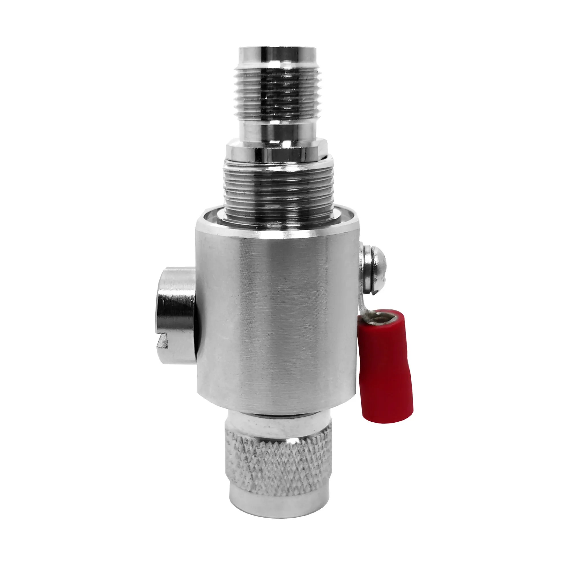
TNC Female: Panel-Mount Connector for RF Gear
Choosing a tnc female connector for a panel is rarely just a matter of finding the correct mating thread. The connector sits at a mechanical and electrical boundary: it must hold a repeatable RF path while a cable moves, equipment vibrates, technicians mate and unmate the interface, and the installation environment adds moisture, dust, or temperature cycling. For an RF systems engineer, that combination is why connector selection starts with the signal path and installation conditions together.
A TNC interface is the threaded relative of the familiar BNC family. The thread takes longer to engage than a bayonet coupling, but it provides a more secure connection where vibration or repeated handling can loosen a quick-connect interface. TNC is commonly specified for higher-frequency use than standard BNC; however, the usable frequency, sealing level, power handling, and return loss are properties of the particular connector and cable assembly, not guarantees of the interface name alone.
Why a panel-mount TNC female connector is often chosen over BNC
In a static test rack, a BNC may be completely appropriate because it is fast to connect and disconnect. In a vehicle-mounted radio, rail enclosure, mast-top unit, or portable instrument, the coupling can see continuous vibration. A tnc female connector uses a threaded coupling interface that helps retain the mated connection under these conditions. The practical benefit is not that TNC eliminates installation errors; it is that thread engagement gives the installer a more controlled mechanical interface when the application demands it.
Frequency is the second reason. Many common references place standard BNC use below roughly 4 GHz and TNC capability around 11 GHz, depending on construction. Treat those as family-level selection context rather than a link-budget value. Before release, compare the target operating band, VSWR or return-loss requirement, cable type, and the installed geometry against the actual product data. At higher frequencies, a minor discontinuity at the panel transition or an over-tight cable bend can matter more than the connector family label.
In short: select TNC when threaded retention and suitable high-frequency performance fit the whole assembly. Select BNC when quick engagement and the lower-frequency application make that trade-off more useful.
What “female” means on a TNC panel interface
A TNC female panel receptacle is normally the fixed equipment-side interface. It is commonly specified with an external threaded body and a socket-style center contact, but a procurement line should not stop at the word “female.” Confirm standard versus reverse polarity, impedance, mounting thickness, flange or bulkhead geometry, cable termination method, and environmental requirement. A female coax connector that mates physically with the expected cable end is only the beginning; its electrical and mechanical configuration must also match the design.
Reverse-polarity TNC (RP-TNC) is a frequent source of avoidable integration delays. RP-TNC changes the center-contact gender relationship while retaining the threaded outer-coupling style. Standard TNC and RP-TNC should therefore be treated as distinct interfaces in drawings, RFQs, and incoming inspection. Ask the simple question before ordering: is the mating cable end standard TNC or RP-TNC, and is its center contact pin or socket? That check is more valuable than relying on a catalog photo.
Straight, right-angle, and cable-entry choices
A straight panel-mount tnc female connector is often the cleanest choice where there is rear clearance and a cable can leave the enclosure without a sharp turn. A right-angle cable-side mating option can reduce stress when the enclosure is shallow or the cable must run parallel to the panel. Still, a right angle connector is not simply a straight connector bent at 90 degrees. Its internal transition has its own RF behavior, so review the specific return-loss and frequency specification rather than assuming equivalence.
For outdoor communications, inspect the complete mated assembly: connector, gasket or sealing arrangement, cable, strain relief, and any adapter. An environmental claim for the connector body does not automatically transfer to every installed interface. In railway and mobile equipment, also consider cable support and service loops so vibration is not transferred directly into the panel termination.
Where threaded TNC panel connectors earn their place
- Aerospace and defense RF equipment: vibration, environmental exposure, traceability expectations, and defined interface control can make the threaded coupling attractive. Confirm application-specific qualification requirements separately.
- Railway communications and vehicle radios: a retained threaded connection helps address vibration while bulkhead mounting keeps the enclosure interface serviceable.
- Outdoor wireless and antenna systems: TNC is useful where a compact threaded RF connection is needed, provided the complete mated assembly is specified for the exposure.
- Laboratory and portable RF gear: panel-mounted TNC ports can provide repeatable access when test leads or antenna cables must be changed without disturbing the internal layout.
Use adapters to solve an interface problem, not hide one
Mixed-interface systems sometimes require a TNC-to-N or BNC-to-TNC transition. Treat the adapter as part of the RF chain: verify its impedance, frequency limit, mating polarity, mechanical clearance, and the number of interfaces it adds. If an adapter is necessary for serviceability or compatibility, it can be the right choice. If it only compensates for an unclear connector callout, correct the drawing instead.
For a higher-specification TNC option, Worldpeak lists the TNC-ULTRA Miniature TNC Connector as a 50 Ω, 0–8 GHz, stainless-steel, hermetically sealed connector with MIL-STD-348 cited in its product title. This is an example of why buyers should compare the individual part specification with the installation requirement rather than applying one general TNC rating to every design.
A sma female to female connector may be useful in a separate compact SMA test path, but it is not a substitute for a TNC adapter when the installed panel and mating cable are TNC. Keep interface families explicit in the bill of materials and use a confirmed cross-interface adapter only where the signal path genuinely requires it.
Five checks before specifying the part
- Confirm standard TNC versus RP-TNC and the center-contact gender.
- Match the impedance and the connector’s rated frequency range to the operating band.
- Choose the bulkhead, flange, or panel-mount geometry and verify panel thickness.
- Review cable routing, rear clearance, strain relief, and whether a right-angle mating configuration is needed.
- For harsh environments, specify the complete mated and sealed assembly, then request the electrical and material documentation your program needs.
There is no universally suitable tnc female connector. For a vibration-prone, higher-frequency RF port, the threaded TNC format can be a sound starting point. The final choice should be made only after polarity, impedance, panel geometry, frequency margin, cable routing, and environment have been checked as one system.





