 EN

Tunnel Feeder Cable: Signal Coverage Applications
A tunnel feeder cable is not a passive afterthought in a coverage project. It is the RF path that carries energy from a base-station or remote radio connection to antennas, splitters, and distributed antenna system branches. In a tunnel, every meter adds attenuation, access is constrained, and a repair window can be expensive. That is why the tunnel feeder cable decision should begin with the link budget, route length, frequency band, available supports, and the environmental transition at each portal.
For an engineering contractor, the useful question is not simply “which cable is bigger?” It is which tunnel feeder cable keeps loss within the design allowance while remaining practical to pull, bend, clamp, ground, seal, and inspect. The answer can vary between a short equipment-room jumper and a long main feeder serving multiple underground zones.
Where a tunnel feeder cable fits in the coverage chain
A typical tunnel coverage chain includes a signal source or base station, donor or service equipment, main feeder runs, passive components, remote antennas, and sometimes radiating cable. The tunnel feeder cable normally handles the non-radiating transport portion: it moves RF power to the point where the system distributes or radiates it. A radiating cable is different; its engineered outer conductor lets RF energy leak along a route. Mixing those two roles in planning can produce poor coverage expectations.
Low loss matters because feeder loss reduces the power that reaches the antenna side of the link. High shielding also matters: a well-shielded tunnel feeder cable helps control unwanted coupling in crowded cable routes and supports predictable system behavior. Neither attribute replaces sound design, connector workmanship, or acceptance testing. Together, they preserve more of the calculated system margin.
Why diameter and construction change the installation decision
Corrugated copper feeder is commonly selected for fixed infrastructure because the corrugated construction balances electrical performance with a robust installation format. In broad terms, a larger tunnel feeder cable presents lower attenuation and greater power-handling headroom over a comparable run, while also demanding more pathway space and more careful handling. Exact figures must come from the chosen manufacturer data sheet at the operating band and length.
| Feeder option | Where it is often considered | Practical trade-off |
|---|---|---|
| 7/8-inch corrugated feeder | Branch feeders and many medium-length main runs | Useful balance of loss, weight, routing space, and installation effort. |
| 1-5/8-inch corrugated feeder | Longer or higher-power trunk paths | Typically chosen to reduce loss, but needs larger supports, bends, and pulling planning. |
| Smaller flexible coax such as rg402 or lmr195 | Equipment interfaces, short jumpers, and test connections | More flexible, but not a substitute for a long, low-loss trunk tunnel feeder cable. |
The 7/8-inch Corrugated Copper Feeder Cable - 50 Ohm is a relevant starting point when a project calls for a medium-size corrugated path. For pre-cut site runs, a Worldpeak 1-2 feeder Pre-Terminated Cable Assembly can help planners consider how termination work, route measurements, and installation sequencing fit together. These links identify available items; final electrical selection still requires a project-specific data-sheet review.
Loss, shielding, and usable system gain
System gain is a chain result, not a cable label. Every tunnel feeder cable run should be evaluated with the intended band, line length, connector count, splitter loss, antenna gain, and receiver-side margin. Lower line loss leaves more useful energy at the antenna and can reduce the pressure to compensate elsewhere. High shielding supports cleaner RF routing where feeder lines run beside power, controls, and other communications infrastructure.
Do not treat rg402 and lmr195 as interchangeable with a main tunnel feeder cable. rg402 is often considered where compact, robust interconnect geometry is useful. lmr195 is often considered for short flexible connections where handling convenience matters. In each case, verify impedance, frequency performance, connector compatibility, and the actual routing environment. A short lmr195 jumper can be sensible at a cabinet; extending it through a long tunnel route may undermine a loss budget designed around corrugated feeder.
During design review, label each tunnel feeder cable segment by function: trunk, branch, jumper, or test lead. That simple discipline keeps rg402 and lmr195 in their intended short-interconnect roles and prevents a BNC T test adapter from being treated as permanent distribution hardware. It also gives the installation team a clear way to compare a tunnel feeder cable schedule with the drawings before material reaches the tunnel.
Installation checks that prevent costly rework
- Survey the route first. Confirm tray capacity, support locations, portal penetrations, sharp direction changes, and safe pulling access before releasing the tunnel feeder cable.
- Respect bend and pulling limits. Use the selected cable’s published minimum bend radius and pulling guidance. Oversized bends, crushed corrugations, or misaligned clamps can alter mechanical condition and complicate testing.
- Plan grounding and bonding. Place grounding kits according to the design and local requirements, including transitions exposed to lightning or outdoor infrastructure.
- Seal the outdoor transition. At portals, use compatible weatherproofing around connector interfaces and cable entries. Water management must include drip paths, jacket condition, and enclosure sealing—not tape alone.
- Label and test every section. Record route IDs, connector locations, and test results so later maintenance does not rely on memory.
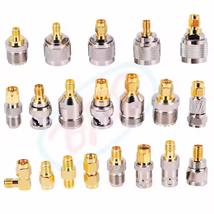
A BNC T adapter may be useful in a controlled test or temporary measurement setup, but it should not be assumed to be a permanent substitute for a designed RF distribution component. As with the tunnel feeder cable itself, connector style, power level, environmental exposure, and the approved network layout determine whether a BNC T belongs in the job.
Field handover note: The drawing set should identify each tunnel feeder cable route, its termination, and its test point. For cabinet work, record whether rg402 or lmr195 is the approved jumper, and identify any BNC T used only for commissioning. During turnover, compare every tunnel feeder cable label to the route schedule; this makes later fault isolation more efficient. A replacement tunnel feeder cable should match the approved assembly rather than be selected by diameter alone.
Specify a cable package, not just a cable size
A reliable tunnel feeder cable scope should state impedance, conductor construction, operating bands, required length allowance, connector type, grounding hardware, clamps, weatherproofing materials, labeling, and test expectations. It should also identify where custom cutting, pre-termination, or protective jacket treatment is needed. This is more useful to a procurement team than a generic request for “feeder cable,” because it reduces field decisions made after access time has begun.
For a tunnel feeder cable project, ask suppliers to confirm the applicable data sheet, available custom lengths, connectorization options, and outdoor sealing process before purchase. Then verify the delivered configuration against the drawing during incoming inspection. The result is a clearer installation plan, more defensible maintenance record, and a better chance that measured coverage matches the original link budget.





