 EN

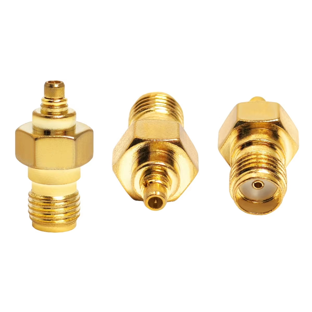
Using Rf To Coax Adapter in 5G Base Station Deployments
A 5G site rarely fails because an adapter looked unfamiliar. It fails because a small interface decision adds an impedance discontinuity, exceeds a frequency limit, loosens under vibration, or admits moisture into a feeder path. An rf to coax adapter is therefore not a generic conversion part. It is a controlled transition between two defined RF interfaces, and its selection belongs in the same review as cable loss, antenna ports, grounding, and weather sealing.
As an RF systems engineer, I start with the full signal path rather than the connector family name. The practical question is not simply “will this rf to coax adapter mate?” It is whether the source, cable, adapter, and load retain the required impedance, bandwidth, power margin, and mechanical reliability once installed on the tower or inside the radio enclosure.
First, separate RF adaptation from signal conversion
An rf to coax adapter changes an RF connector interface or gender while preserving an RF transmission path. It does not turn a coaxial RF signal into Ethernet, USB, or a digital network stream. Searches for convert coax to ethernet or a coax to usb converter often point to active equipment such as Ethernet-over-coax bridges, video capture devices, or modems. Those products may be useful elsewhere in a site, but they are not substitutes for an RF interconnect adapter at a radio-frequency port.
That distinction matters in a 5G deployment. A passive rf to coax adapter should be selected by impedance, frequency, return loss or VSWR, power, interface geometry, and environment. An active converter must also be selected by protocol, bandwidth, power supply, and endpoint compatibility. Mixing the two requirements in an RFQ is an easy way to receive a physically plausible but electrically wrong component.
Build the selection around the operating window
No single rf to coax adapter fits every installation. The right choice depends on the highest operating frequency, the continuous and peak RF power, the impedance of the complete path, the available mounting space, and the expected exposure. Establish those limits before comparing connector bodies.
| Interface family | Where it is often useful | What to verify before selection |
|---|---|---|
| SMA | Compact radio modules, test ports, and higher-frequency internal or short-jumper paths. | Exact frequency rating, 50-ohm configuration, mating-cycle requirement, and cable bend relief. |
| N type | Robust outdoor feeder and antenna-side RF paths where a larger threaded interface is acceptable. | Exact impedance, power rating at operating frequency, sealing arrangement, and compatible gender. |
| BNC | Quick-connect test, video, security, and lower-frequency service applications. | Whether the path is 50 or 75 ohms; bnc to coax describes a mechanical transition, not automatic impedance compatibility. |
| TNC | Threaded, vibration-conscious RF links in communications and industrial equipment. | Exact part frequency window, coupling torque, polarization, and exposure rating. |
The family names are useful starting points, not guarantees. Standard BNC products are commonly seen in lower-frequency quick-connect work, while specialized variants can extend further. TNC documentation also commonly shows threaded 50-ohm designs through 11 GHz, with some extended designs higher; the exact data sheet governs. For a 5G radio path, do not infer a usable frequency ceiling from a connector’s appearance or family alone.
Impedance and power are system checks, not labels
Most radio and feeder systems use a 50-ohm path. Video and some broadband architectures may use 75 ohms. An rf to coax adapter has to match the designed impedance of the path, not merely connect two compatible-looking threads. A 75-ohm N interface, for example, is not automatically appropriate in a 50-ohm radio chain. The CMS-confirmed RF-N-75B low-PIM 75-ohm N connector is specified to 6 GHz in its product record, which makes the principle visible: confirm impedance as deliberately as frequency.
Power needs the same discipline. Every interface introduces an additional contact pair and a possible thermal point. Use the manufacturer’s power rating at the actual frequency, cable type, ambient temperature, and duty cycle. Where a feeder path genuinely uses the stated interfaces and operating conditions, the CMS-confirmed 7/16 DIN female to N male high-power RF connector is specified for 0–3.5 GHz and 3 kW at 2.5 GHz. That is a configuration-specific example, not a blanket rating for every rf to coax adapter or every 5G band.
Choose mounting and protection with the site in mind
For a compact indoor radio, a low-profile SMA transition may solve a space constraint but create an unwanted side load if the cable is unsupported. For an exposed feeder, a threaded N-type or TNC transition can provide more secure coupling, provided the mating hardware and sealing scheme are compatible. BNC can be practical for serviceable security or test points, but its bayonet coupling should be evaluated against vibration, pull load, and the required operating band.
Specify the rf to coax adapter with its mounting plan: straight, right-angle, bulkhead, or cable-mounted; free-hanging or strain-relieved; indoor, cabinet, rooftop, or coastal. If exposure is expected, define weatherproofing at the assembly level. A connector body alone does not seal a cable junction. Compatible boots, tapes, gaskets, drip loops, and grounding practices are part of the installation design.
Install and verify the complete RF transition
- Confirm the interface map. Record each port’s connector family, gender, polarity where applicable, and 50- or 75-ohm requirement before unpacking the adapter.
- Inspect and clean. Check center contacts, dielectric surfaces, threads, and cable braid termination. Do not mate a contaminated or visibly damaged rf to coax adapter.
- Support the cable. Respect the cable’s bend radius and prevent the cable mass from loading a small connector or adapter body.
- Use the specified torque. Follow the component manufacturer’s torque guidance rather than overtightening by feel; excessive torque can damage interfaces just as surely as a loose coupling can raise instability risk.
- Protect outdoor joints. Apply the approved weatherproofing sequence after electrical mating, and provide a drainage-friendly route rather than trapping water at the joint.
- Measure after installation. Verify the completed path with the appropriate return-loss/VSWR and insertion-loss test method for the band. Recheck after any rework or suspected cable movement.
Use a concise RFQ checklist
A useful RFQ lists the two interface ends, gender/polarity, impedance, operating frequency range, power at frequency, cable type, mounting style, environmental exposure, required documentation, and verification method. It should also say whether the request is for a passive rf to coax adapter or for an active solution to convert coax to ethernet or connect a coax to usb converter. That one clarification prevents a large class of sourcing errors.
Worldpeak supports RF connector and cable-assembly selection across standard interfaces including SMA, N type, BNC, and TNC, with pre-shipment electrical test capability for cable assemblies. Share the full path and operating envelope, not just the two connector names. With that information, an rf to coax adapter becomes a documented engineering transition rather than the weakest unknown in a 5G base-station link.





