 EN

Using Shielded Feeder Cable in 5G Base Station Deployments
For an RF systems engineer, a feeder run is more than a line item between radio and antenna. It is part of the link budget, part of the interference-control plan, and often one of the least convenient items to replace after a tower, rooftop, or indoor distributed antenna system (DAS) is commissioned. A shielded feeder cable helps carry RF energy while keeping the signal path better isolated from its surroundings. In 5G work, selection has to account for attenuation, shielding continuity, passive intermodulation risk, mechanical routing, and the reality of servicing a cable years later.
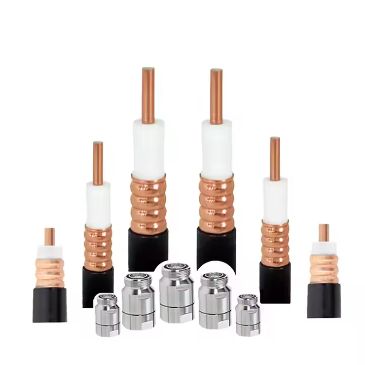
The phrase can be confusing because many search results describe shielded control cable rather than RF feeder. In a base-station RF path, the relevant assembly is normally a 50-ohm coaxial feeder with a continuous outer conductor. Corrugated copper designs are common where long outdoor runs, substantial transmit power, and durable installations are involved. The outer conductor contributes to shielding, but good system performance still depends on correctly matched connectors, clean interfaces, grounding practice, and weather sealing.
Where feeder cable fits in a 5G RF architecture
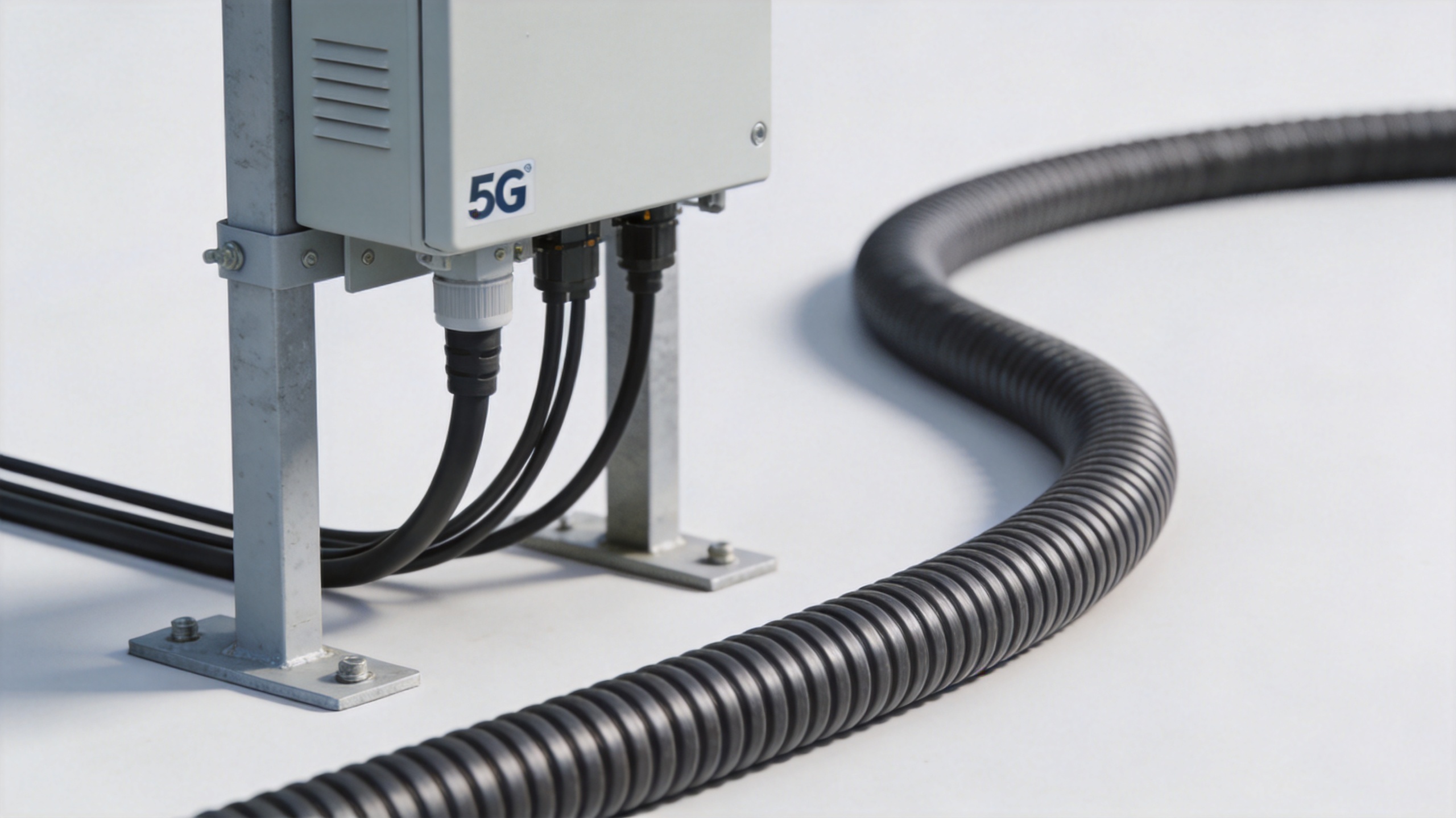
At a macro site, a shielded feeder cable may run from radio equipment to an antenna system, through a feeder window, along a tower or rooftop route, and into antenna jumpers. In some modern architectures the radio is mounted close to the antenna, shortening the high-power feeder section. That does not eliminate cable-selection work: jumpers, remote-radio interconnects, and site-specific routing still need controlled impedance and appropriate environmental protection.
For indoor distribution, the cable network serves a different physical layout. A DAS may use backbone feeder runs to reach floors or zones, then branch through passive components and smaller cables. The selection question is therefore not simply “what is the lowest-loss cable?” It is whether a given cable diameter, bend capability, connector family, and installation method suit the planned route without creating difficult transitions or inaccessible failure points.
Why low loss and shielding must be evaluated together
Insertion loss accumulates across the RF path. A longer run, a higher operating frequency, and additional connectors each deserve attention in the link budget. Larger corrugated feeder cable is commonly chosen when a long trunk run needs lower attenuation, while a smaller cable can be more practical in congested paths or for shorter sections. Use the manufacturer’s frequency-specific attenuation tables rather than assuming one diameter is suitable for every band or route.
Shielding is equally practical. A continuous outer conductor can help confine RF energy and reduce susceptibility to nearby electromagnetic activity, but it is not a substitute for sound bonding and connector workmanship. A damaged jacket, a deformed corrugation, or a poorly prepared connector can undermine the very continuity the cable was selected to provide. The jobsite acceptance process should include visual checks, connector torque according to the connector supplier’s instructions, and electrical verification appropriate to the project.
Choosing between 7/8-inch and 1-5/8-inch corrugated runs
For many outdoor base-station applications, 7/8-inch corrugated cable provides a useful balance of low-loss capability and manageable handling. It can fit projects where installers need a durable trunk cable without the weight and routing constraints of a larger size. A documented option is the 7/8" Corrugated Copper Feeder Cable - 50 Ohm; verify its current data sheet, connector compatibility, and site requirements before specifying it.
Moving to 1-5/8-inch corrugated cable can make sense for high-power or longer macro-cell feeder runs when the link budget benefits justify the added diameter and weight. The tradeoff is mechanical: larger cable requires wider bend space, stronger support planning, more deliberate pulling procedures, and suitable entry hardware. It should not be forced through a route designed for a smaller cable simply because its attenuation figure is attractive.
One practical approach is to model the route in segments. Put the lowest-loss trunk cable where distance and power make it valuable, then use appropriately specified flexible jumpers where equipment connections or tight geometry require them. Pre-terminated assemblies can also reduce field termination work when lengths, connector interfaces, and pulling protection are planned in advance. For example, review the available details for the Worldpeak 1-2 feeder Pre-Terminated Cable Assembly with the supplier before using it in a particular design.
Specify the assembly, not only the cable
A request for a shielded feeder cable should define more than diameter. State nominal impedance, operating frequency range, run length, attenuation limit at the relevant frequencies, connector interfaces, indoor or outdoor exposure, jacket needs, grounding accessories, and any project-specific fire, material, or documentation requirements. Where flexible interconnects are needed, the applicable portions of the IEC 61196 RF coaxial cable family can be a useful reference point, alongside the project’s own approved specification.
Custom lengths and mixed interfaces can remove unnecessary adapters, but they must be engineered as an assembly. Do not treat rg11 as an interchangeable substitute for a 50-ohm base-station feeder: cable impedance, intended use, and connector compatibility must match the RF design. Likewise, a bnc crimp termination or an rpsma male interface may be appropriate for selected low-power equipment or test paths, but neither should be assumed suitable for a main feeder without checking power, frequency, mating, and environmental requirements.
Outdoor installation, waterproofing, and maintenance
Outdoor longevity is decided at transitions. Preserve the cable’s minimum bend radius, use supports that prevent crushing or abrasion, and leave a controlled service loop where future replacement is realistic. Keep water paths out of connector interfaces by following the approved weatherproofing sequence for the specific connector system. Sealing materials, connector boots, grounding kits, and entry panels should be compatible with the cable and local site practice; a wrapped connection is not automatically a watertight connection.
Before handover, document cable IDs, route segments, connector locations, grounding points, and test results. During maintenance, inspect jackets, supports, seals, and connectors after severe weather or site work. Compare new sweep or VSWR results with commissioning records rather than relying only on a visual inspection. That baseline makes it easier to isolate whether a loss of margin is caused by a feeder, a jumper, a connector, or another part of the RF chain.
RF documentation cross-check
Keep terms in the bill of materials tied to their intended circuit function. The short cross-check below prevents feeder, legacy video-cable, and low-power interface language from being mixed without an engineering review.
| RF trunk record | Legacy-cable record | Test-interface record | Accessory-interface record |
|---|---|---|---|
| shielded feeder cable | rg11 | bnc crimp | rpsma male |
| shielded feeder cable | rg11 | bnc crimp | rpsma male |
| shielded feeder cable | rg11 | bnc crimp | rpsma male |
| shielded feeder cable | rg11 | bnc crimp | rpsma male |
| shielded feeder cable | rg11 | bnc crimp | rpsma male |
| shielded feeder cable | rg11 | bnc crimp | rpsma male |
| shielded feeder cable | rg11 | bnc crimp | rpsma male |
| shielded feeder cable | rg11 | bnc crimp | rpsma male |
A procurement checklist for the next deployment
- Calculate the path loss at the operating frequencies and planned run length.
- Choose 7/8-inch, 1-5/8-inch, or a mixed cable architecture based on electrical and installation constraints.
- Confirm 50-ohm impedance, connector interfaces, and all adapter transitions.
- Specify outdoor jacket, sealing, grounding, support, and entry requirements together.
- Request assembly documentation and electrical test data when the project requires incoming verification.
- Plan inspection access so the shielded feeder cable can be maintained rather than merely installed.
A sound feeder choice is one that preserves the RF budget and remains installable, sealable, and serviceable in the real site environment. Treat cable size, shielding continuity, interfaces, and field workmanship as one decision, and the resulting 5G RF path will be easier to commission and maintain.





